Appendix C — EA21 Imager
112 ED40 Decode Board Integration Guide
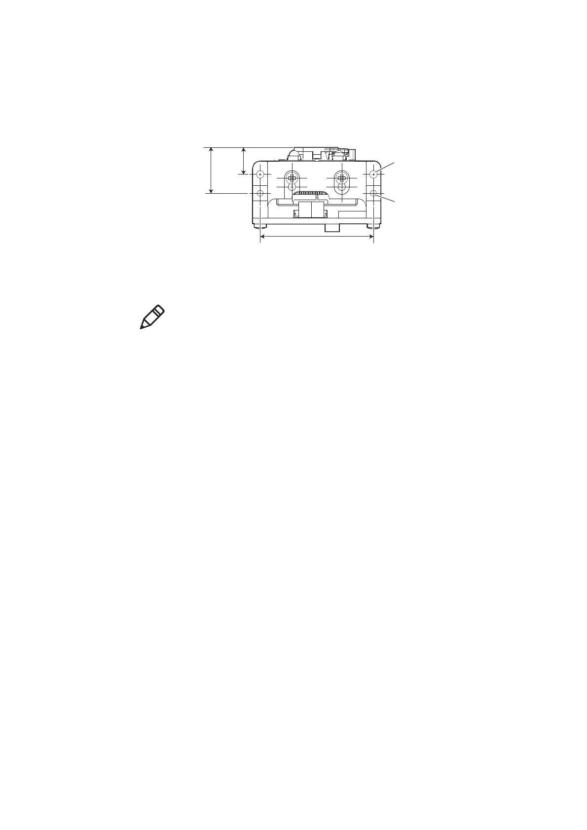
Mounting and Positioning Holes
There are two positioning holes located on the mounting bracket as shown below.
Use 2 M2 screws with a minimum engagement of 4 mm / 0.16 in to mount the
imager + ED40 into your design.
EA21 + ED40 Mounting and Positioning Holes
Positioning holes (2 places)
diameter 2 mm/0.08 in,
depth 2.5 mm/0.10 in
Hole for M2 screw (2 places)
min. engagement 4 mm/0.16 in
30 mm
1.18 in
7.1 mm
0.28 in
12.1 mm
0.48 in
Note: The EA21 can also be used unmounted with the ED40 decode board. The
ribbon cable should be 50.8 cm (2 in.) in length with a maximum of 10.16 cm (4
in.). See “Imager Ribbon Cable Connecting to ED40” on page 114 for more
information.