Chapter 3 — Electrical Integration
ED40 Decode Board Integration Guide 17
Power Enable
The Power Enable signal is an external hardware driven signal that switches the
scanner (decode board + imager) power on (when low) and off (when high),
except when writing setup parameters in non-volatile memory. To do this, the
scanner activates the Power Hold signal, an internal software driven signal, that
allows the scanner to stay on even if the Power Enable line is high (off)
.
The Power Hold signal is an internal software driven signal that can be
configured using EasySet or the Power Hold ISCP command (Setup 70, 47).
When Power Hold is disabled, the scanner activates the Power Hold signal only
when writing setup parameters in non volatile memory.
When Power Hold is enabled, the scanner activates the Power Hold signal:
• at start up
• at the beginning of a reading session
• after reception of a correct ISCP frame
• while writing setup parameters in non volatile memory
The scanner deactivates the signal:
• at the end of a reading session
• after receiving a Sleep command
10 Input CTS/Detect in 2 The host authorizes transmission on TXD line
(RTS/CTS hardware protocol).
11 Output Buzzer Used to drive the external buzzer with 50% duty
cycle square wave with a frequency range from 0.1
kHz to 4.0 kHz.
Contact 11 does not provide enough current (4
mA) to drive the buzzer. You must add a
transistor between contact 11 and the buzzer. For
more information, see “Buzzer” on page 19.
12 Input Detect in 0 Must be connected to ground for an RS-232
connection.
Must be connected to Vcc for a USB connection.
Contact Assignment—Host Connector
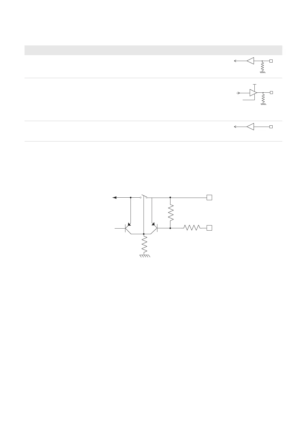
Contact I/O Name Description Electrical Equivalent
100 K
Vcc in
Data out
Enable
Data in
47K
47K
Power enable
Vcc in
Power hold