Goodrive300-01A-RT series integrated machine RS485 communication LCD keypad
-105-
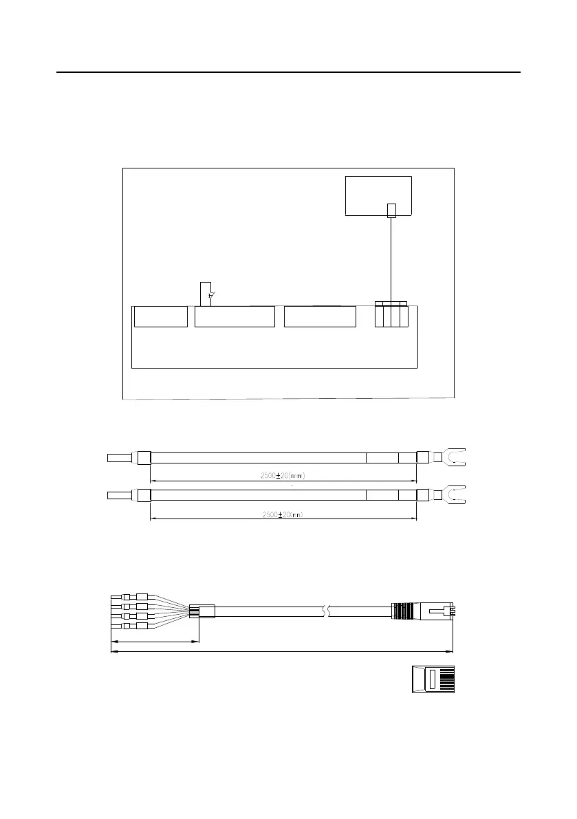
B.3 RS485 communication cable
B.3.1 Wiring description
Please use the provided RS485 communication cable, of which one end is connected to the keypad
network port and the other is connected to Goodrive300-01A-RT VFD control board user terminal
(CN7). Do not use the ordinary network cable.
TA1
TC1
RO1A
RO1C
S1
S2
S3
PTC
COM
Y1
P1+
P1-
PT1+
PT1-
PT2+
PT2-
GD300-01A-RT control board
Output voltage 220AC
Multi-function terminal
Pressure sensor
interface 24V 4-20mA
PT100 temperature
sensor interface
485 keypad
RS485
communication
cable
COM
Emergency stop signal wiring
+24V
GND
485+
485-
+24V
GND
485+
485-
Network
port
CN7
Figure B-4 RS485 communication cable connection diagram
B.3.2 Cable description
Emergency
stop signal
Emergency
stop signal
Figure B-5 Emergency stop cable diagram
Note: The emergency stop cable is used for emergency stop control when a device fault occurs and it
is often connected to the S1 terminal and COM terminal.
2500±15(mm)
485+
+24 V
485-
GND
70±10(mm)
棕
棕白
绿
蓝白
蓝
绿白
橙
橙白
1
2
3
4
5
6
7
8
8
1
Figure B-6 RS485 communication cable diagram
 Loading...


