Goodrive300-01A-RT series integrated machine Commissioning instruction
-16-
4 Commissioning instruction
4.1 HMI commissioning
4.1.1 System wiring
485+
485-
GND
+24V
U2 V2 W2
M
COM
S3
S2
S1
Emergency stop
PT1-
PT1+
P1-
P1+
PT100
Discharge
pressure
PT2-
PT2+
PT100
Oil gas temperature
Auxiliary temperature
Cooling fan
R
S
T
PE
T
S
R
S
T
U1 V1 W1
M
Main motor
220V/TA1
0V/TC1
Solenoid
coil
GD300-01A-RT
HMI
Fan current detection
RO1A
RO1C
PTC
Y1
COM
PW
+24V
J9
ON
J2
V I
J1
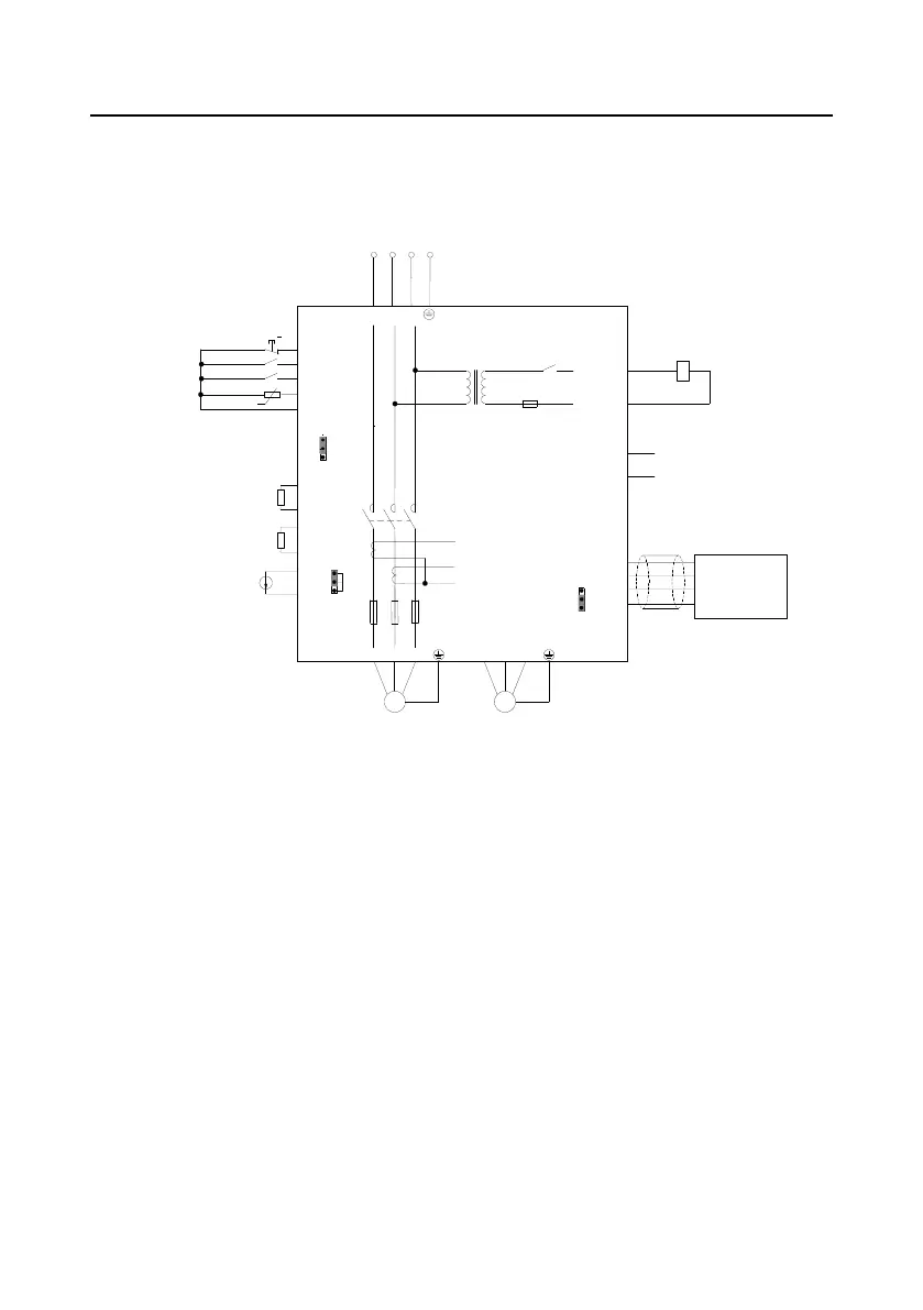
Figure 4-1 Wiring diagram for HMI + GD300-01A-RT VFD
4.1.2 Commissioning steps for HMI
It is recommended to use HMI special for Goodrive300-01A-RT series VFDs to display and
commission.
Note: All the parameters displayed in the interfaces are subject to actual displayed content.
1. Perform wiring according to Figure 4-1 and ensure that the VFD for air compressor and the housing
of the air compressor are grounded properly.
2. After power up, the following interface is displayed.
 Loading...


