Goodrive300-01A-RT series integrated machine Wiring instruction
-9-
3 Wiring instruction
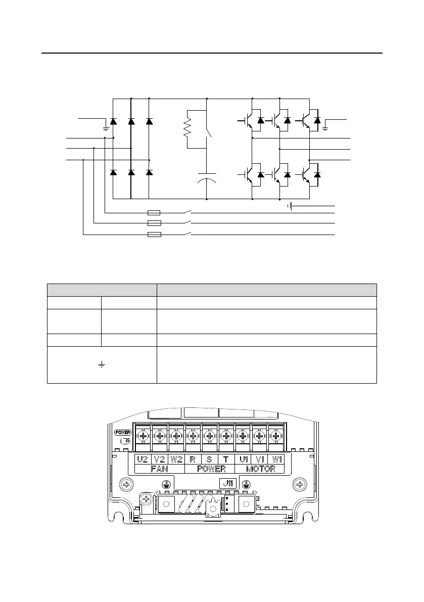
3.1 Main circuit wiring and terminal description
Figure 3-1 Main circuit wiring diagram
Table 3-1 Main circuit terminal description
3PH AC input terminals, connected to the grid
3PH AC output terminals, connected to the main motor of the
air compressor
3PH AC output terminals, connected to the fan
Each machine must be grounded. The grounding is
implemented through the two PE terminals on the machine,
and the grounding resistance is less than 10Ω.
Figure 3-2 Main circuit terminal diagram for 7.5kW VFD models
 Loading...


