Goodrive300-01A-RT series integrated machine HMI
-139-
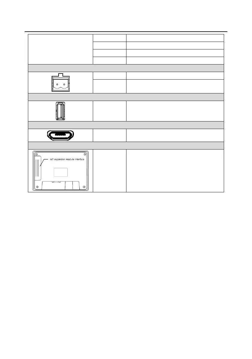
RS485 terminals (Pins 1–2, from left to right)
Used to connect external peripherals such as
the USB disk and barcode scanning device.
Used for program download and debugging.
Expansion
module card
slot
Supported modules: FLink, FLink-2G,
FLink-4G, and FLink-WiFi
C.3 Wiring description
In order to drive and manage the air compressor better, use the provided RS485 communication
cable, of which one end is connected to the touch screen power supply port and DB9 serial port
terminal and the other is connected to Goodrive300-01A-RT VFD control board user terminal (CN7).
Do not use the ordinary network cable.
 Loading...


