Goodrive300-01A-RT series integrated machine Commissioning instruction
-23-
A2
B2
26
25
2
1
PT100
31
30
23
22
Temperature sensor
Pressure
sensor
220AC
Fan
MM
Main motor
U
1
Solenoid
valve
TC1
TA1
R
B1
A1
+24V
OUT
+24V
J7
+24V
CME
COM
J3
ON
J2
48 5-
48 5+
14
6
VFD fault output
W
2
V
2
U
2
W
1
V
1
S3
Y
48 5-
48 5+
GN D
+2 4V
Solenoid valve control
IoT module
S
T
S1
S2
MAM6080M
Fan start/stop control
CO M
12
VFD terminal start/stop
13
18
11
GD300-01A-RT
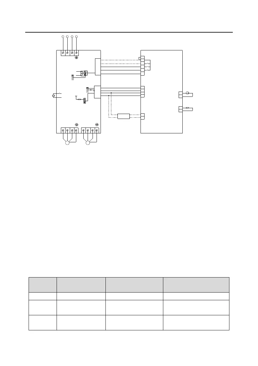
Figure 4-14 Wiring diagram for Plot controller 6080M + GD300-01A-RT VFD
4.2.2 Commissioning steps
Goodrive300-01A-RT series VFD can be used with Plot controller. The commissioning procedures
are as follows.
1. Perform wiring according to the wiring diagram based on onsite needs. Generally, start and stop
the master in communication control. It is recommended to use the terminal to control start and stop
of the main motor when the interference on the sire is strong. To start and stop the main motor in
terminal control, it is necessary to connect COM to S1 in accordance with the dotted line, ensure that
the VFD and air compressor shell are grounded.
2. Set jumpers according to Figure 4-13. Set P06.01=5, set the calibration parameter of Plot controller
(Phase sequence protection value) to 0 and block Phase sequence error 1, as shown in Figure
4-20. Set the hardware parameter of Plot controller pin 6 to Main motor VFD fault NO, as shown in
Figure 4-19. After these parameters are set completely, main motor VFD fault output is available.
3. Set P00.18=1 to restore to default value, and configure the system parameters sequentially
according to Table 4-1.
Table 4-1 System parameter configuration
Upper limit of
running frequency
P00.05–P00.03 (max. output
frequency)
 Loading...


