Goodrive300-01A-RT series integrated machine HMI
-140-
HMI
GD300-01A-RT control board
Touch screen
communication cable
DB9 serial
port terminal
CN7
Power supply
interface
Emergency stop
signal wiring
Power supply cable
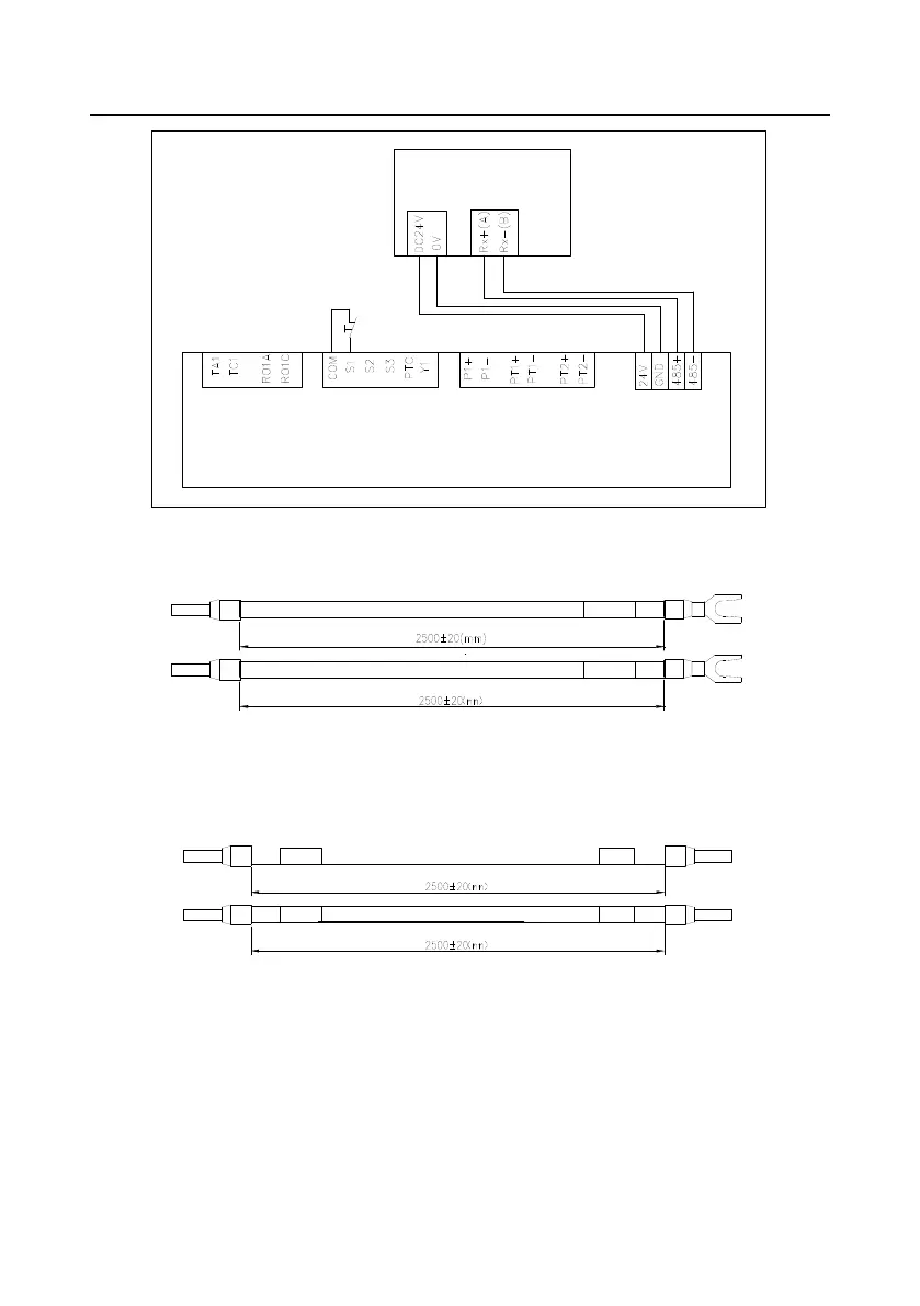
Figure C-1 Touch screen cable connection diagram (standard configuration)
C.4 Cable description
Emergency
stop signal
Emergency
stop signal
Figure C-2 Emergency stop cable diagram
Note: The emergency stop cable is used for emergency stop control when a device fault occurs and it
is often connected to the S1 terminal and COM terminal.
Figure C-3 Touch screen power supply cable diagram
Note: As shown in Figure C-1, the touch screen power supply interface is connected to CN7 of
GD300-01A-RT VFD control board.
 Loading...


