Goodrive300-01A-RT series integrated machine Commissioning instruction
-22-
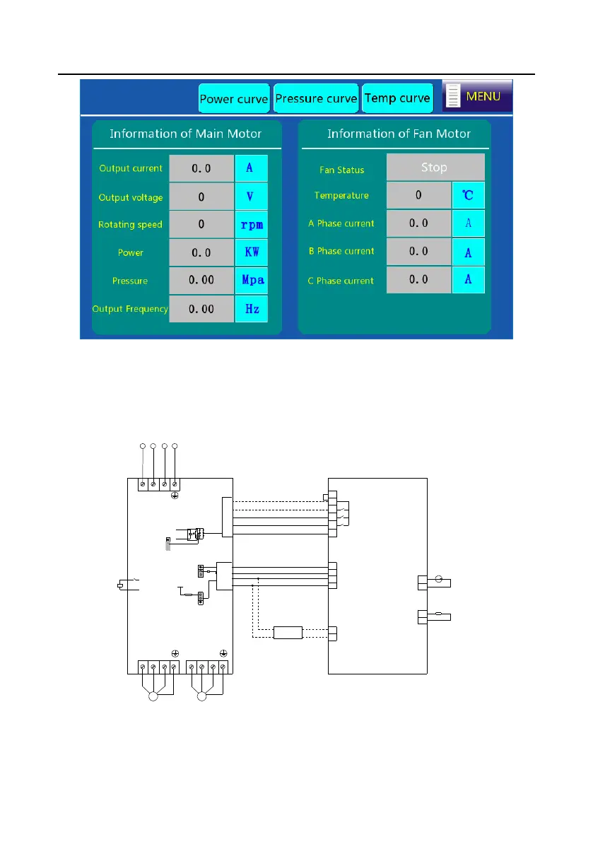
Figure 4-12 Running information interface
12. After adjusting user parameters, factory parameters and maintenance parameters according to
the manual, return to Workspace interface and click Start to run.
4.2 Plot controller adaptation commissioning
4.2.1 System wiring
+24V
GND
IoT module
21
24
23
+ 2 4 V
OUT
+ 2 4 V
J7
B1
A1
A2
B2
9
8
2
1
485-
485+
J2
ON
17
15
VFD terminal start/stop
16
12
COM
6
Solenoid valve control
VFD fault output
Fan start/stop control
S3
22
485-
485+
Y
S2
S1
13
MAM6070M
J3
R
S
Solenoid
valve
TC1
TA1
2 2 0 A C
COM
CME
+ 2 4 V
T
Main motor
M
Fan
M
U
2
V
2
W
2
U
1
V
1
W
1
GD300-01A-RT
Temperature sensor
Pressure
sensor
P T 1 0 0
Figure 4-13 Wiring diagram for Plot controller 6070M + GD300-01A-RT VFD
 Loading...


