Goodrive300-01A-RT series integrated machine Wiring instruction
-15-
Y
CME
+24V
●
●
●
J3
•
•
•
•
+24V
COM
COM
Load
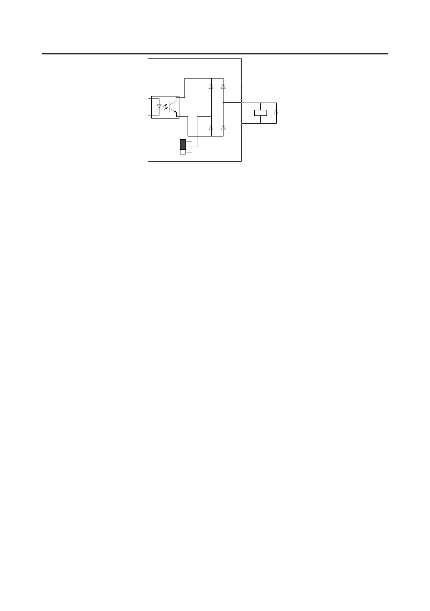
Figure 3-11 Y terminal output (electrical level by default)
When digital output uses OC output, set J3 according to Figure 3-10 and short connect CME to COM.
When digital output uses low electrical level output, set J3 according to Figure 3-11, and short
connect CME to +24V.
When the type of load to be driven by the digital output terminal is a relay, absorber diodes shall be
configured at both ends of the relay coil. Ensure that polarities of the diodes are connected properly,
otherwise the damage to the 24V DC power supply may occur.
Note: The driving capability of this terminal is no more than 50mA current.
 Loading...


