Goodrive300-01A-RT series integrated machine Wiring instruction
-14-
Terminal for
connecting RS485
communication
terminal resistors
ON corresponds to the connection of terminal
resistors. No terminal resistor is connected by
default.
Terminal for short
connecting PE to GND
No short connection is by default.
Note: When the solenoid valve coil power exceeds 15W, the power frequency transformer inside the
integrated machine needs to be customized or independently connected with an external 220VAC
power supply.
●
●
●
COM
+24V
PW
COM
+24V
•
•
S1
S2
•
J9
COM
+24V
PW
COM
+24V
•
•
S1
S2
•
●
●
●
+24V
J9
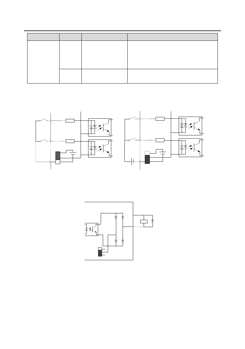
Figure 3-8 Internal power (NPN mode) Figure 3-9 External power (PNP mode)
When digital input uses internal +24V, set J9 according to Figure 3-8, and short connect +24V to PW.
When digital input uses external +24V, set J9 according to Figure 3-9, and short connect COM to PW.
Y
CME
+24V
●
●
●
J3
•
•
•
•
+24V
COM
COM
Load
Figure 3-10 Y terminal output (OC output)
 Loading...


