45
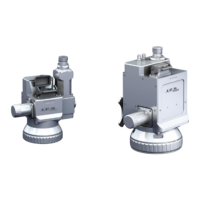
Figure 5-11 Camera Arm Module Image Adjustment
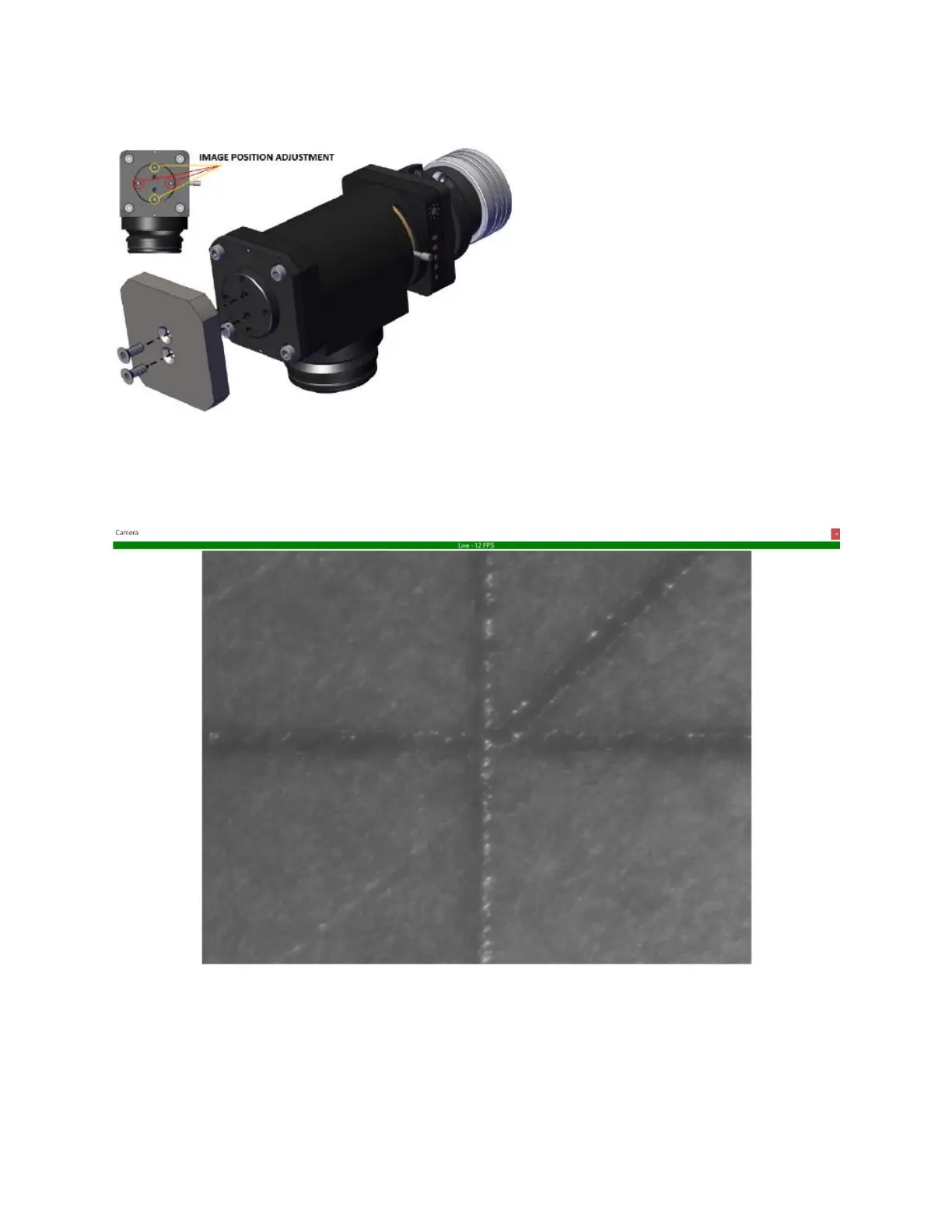
15. Once adjustments have been made, the image should look similar to what is pictured in Figure
5-12.
Figure 5-12 Aligned Camera Image
16. Users can now modify image settings and add crosshairs as desired.
a. For the HD camera, plug the provided controller into the camera and follow the
onscreen menu items.
b. For the USB camera, adjustments are made on the computer.
c. Ethernet camera adjustments are made in IPGScan.