4-41
Multilayer Vector Density
・Function・ The number of the displayed multilayer vector is thinned out on
the profile screen. It is set to 1 (1/1=100% display) usually.
Setting value: [ 1/1 2 4 8 16 Display OFF ]
For instance, when the multilayer current up to 200m in
depth is displayed, about maximum 100 current vectors are
displayed. At this time, the profile display becomes 1/1 when 1
is selected, and 100 all is displayed. When it is 4, similarly it is
thinned out, and 25 current vectors in all for 4 are displayed in 1/4.
Only the vector of A-E of five layers is displayed without
displaying the multilayer current vector when Display OFF it.
The setting of the M. Lay. Vector Density is common in both of the
profile 1 screen and profile 2 screens.
Operation Standard Menu: ”Multi-Layer Profile Picture setting” menu/Vector Density: 1/1 Times
Selection Frame Menu: ”Profile 2 graph” menu/ Vector Density: 1/1 Times
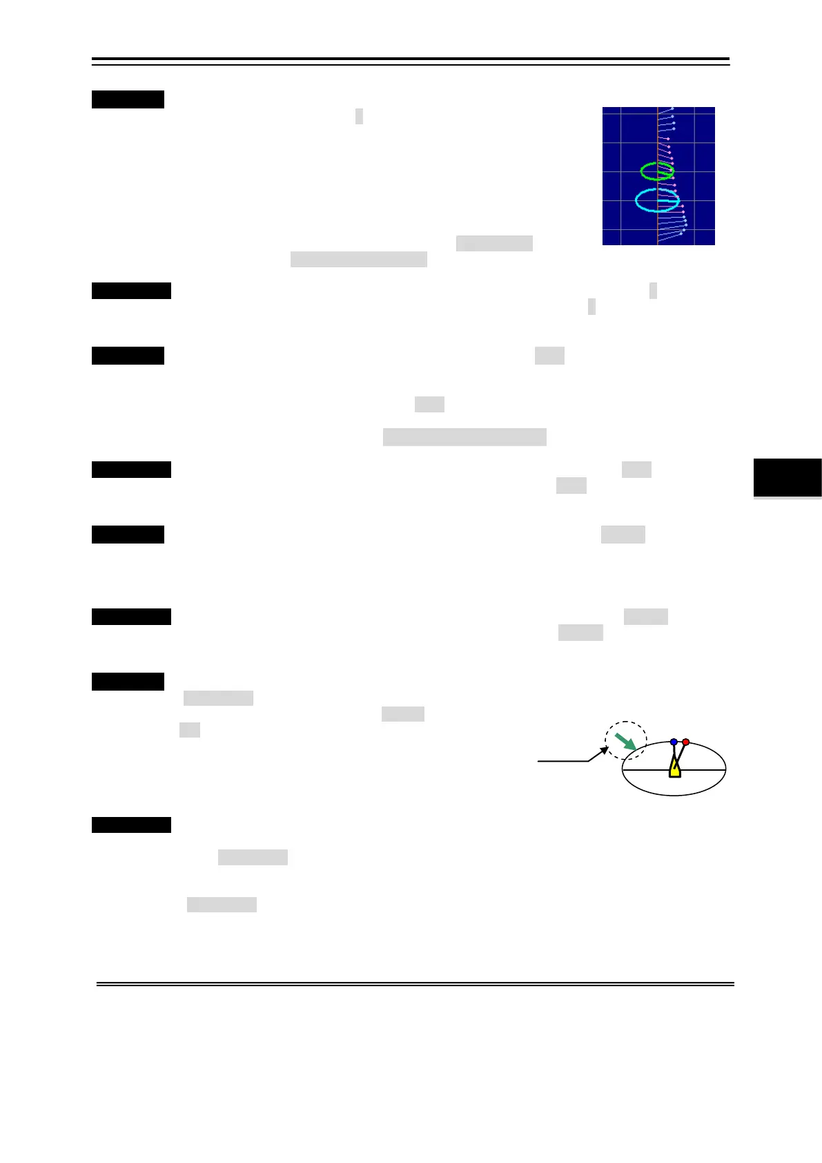
Multilayer Vector Color
・Function・ The vector color of the multilayer current is selected from [Light / Dark].
The display color of the multilayer current vector is displayed by two colors (Red and Blue)
on profile 2 screens (ellipse display).
This red and blue are selected from a Light / Dark. We can use it properly at daytime and
nighttime.
Refer to the above-mentioned “View Point: Vertical Angle” for the display color of the
multilayer current vector.
Operation Standard Menu: ”Multi-Layer Profile Picture setting” menu/Vector color: Light
Selection Frame Menu: ”Profile 2 graph” menu/Vector color: Light
Multilayer Vector Width
・Function・ The thickness of the vector of the multilayer current is selected from [Narrow/Wide].
The thickness of the multilayer current vector can be selected from Narrow/Wide on profile
2 screens as well as the “Vector Color”.
When the number of the displayed multilayer current vector is thinned out and displayed, it
becomes easy to expect being make it to Wide.
Operation Standard Menu: ”Multi-Layer Profile Picture setting” menu/Vector width: Narrow
Selection Frame Menu: ”Profile 2 graph” menu/Vector width: Narrow
Wind Direction Mark
・Function・ The wind direction mark is selected from
[Display ON/OFF]. (*1)
It can be selected whether to display
ON the wind direction arrow in the
bearing display chart (Right Fig. 4.7.1)
on profile 2 screens.
When the velocity of the wind is 0 m/sec
(calm), the wind direction arrow is not
displayed.
Operation Standard Menu: ”Multi-Layer Profile
Picture setting” menu/Wind direction
Mark: Display ON
Selection Frame Menu: ”Profile 2
graph” menu/Wind direction Mark:
Display ON
*1 It is necessary to connect the sensor for the display of data of wind direction/wind speed.
Set to "The anemometer is connected" when you connect the wind direction/wind speed sensor. Refer to 7.1.2 “NMEA0183
Input setting”
Fig. 4.7.1 Bearing Display
Wind Direction Mark :
In the example of the display, it
becomes north-west winds.