9-3
9.1 Warning
There are two kinds of warning (measurement alarm (*1) and a warning). When the abnormal alarm
message is displayed, the current data or the shoal of fish image cannot be correctly measured. Stops
using and then contact shop, agency or our each branch and office that purchased it when the symptom
is not repaired even if it treats it according to the message.
9.1.1 Warning Display
・Function・ When abnormality is found by the equipment unit and the system, "Warning message" is
displayed with the alarm sound.
Operation Warning disappears when the [BUZZER] key is pushed. It is possible to set it to
non-display by the menu. (*1)
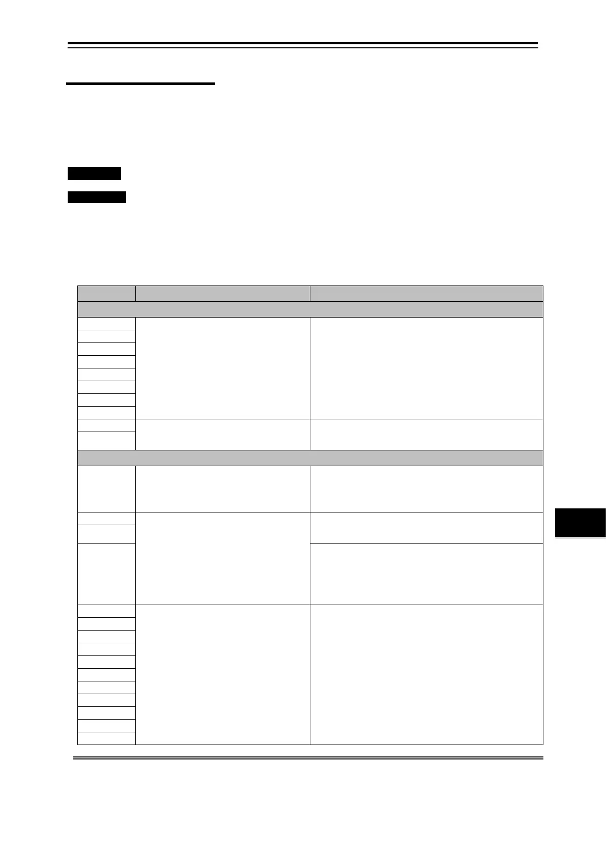
The warning item table is shown below.
Warning No: The warning number is common with self test and warning histor y. (*2)
Warning Contents: The outline of warning is displayed.
Countermeasure: The countermeasure to warning is displayed. Turn off the power supply
and request the repair when not repaired.
DSP
Signal processing unit stopped.
Please reboot after having switched it off once.
When it still abnormal.
Please ask it for repair after power switching off.
"COM communication" with the
Signal processing unit is unstable.
Please reboot after having switched it off once.
Digital System Communication
"COM communication" with the
signal processing unit is not
Please reboot after having switched it off once. Check
whether a connector of "COM" does not connect off.
"USB communication" with the
signal processing unit is not
possible.
Please reboot after having switched it off once. Check
whether a connector of "USB" does not connect off.
Please reboot after having switched it off once. Check
whether a connector of "USB" does not connect off.
When it still abnormal.
Please ask it for repair after power switching off.
Signal processing unit stopped.
Please reboot after having switched it off once.
Please ask it for repair after power switching off.
*1 Refer to 5.1 “Measurement Alarm Display”. /7.1.8 “Alarm Display Setting”
*2 Refer to 9.2.1 “Self Test Screen”. /9.2.2 “Warning History Screen”