4-19
Wind Direction Arrow (*1): Display/Non-display
・Function・ It is set whether to display the wind direction arrow on the circle graph.
Display: The arrow of the example ⑤ is displayed in figure. The wind blows from the
direction of the arrow.
Non-display: The wind direction arrow is not displayed.
Operation Standard Menu: Current screen setting menu/Wind direction arrow: Display/Non-display
Selection Frame Menu: Current circle graph menu/ Wind direction arrow: Display
/Non-display
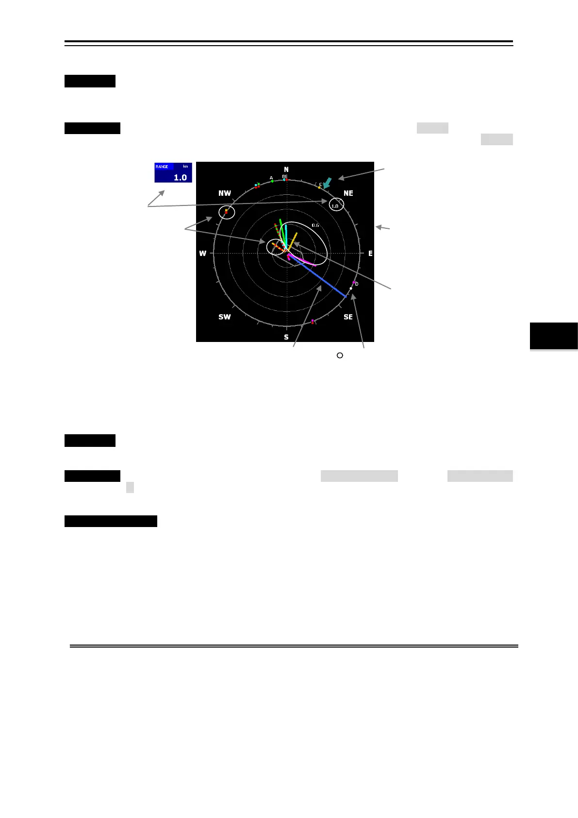
Fig. 4.2.1 Current Circle Graph
4.2.2 Current Echo Graph Setting
・Function・ The display of the echo graph of current 3 screens is set.
Setting item: Echo Graph depth range, mode selection, and SN value high・low, display
color, background color
Operation Standard Menu: [MENU] key/Menu screen/Display setting ≫/[ENT] key/Current screen
≫/[ENT] key/Current screen setting menu
Selection Frame Menu: [
□] key/ Enclose “Echo graph” with the frame /[MENU] key/Echo
graph setting menu
About echo graph
The reflection of the supersonic wave transmitted in four directions is caught in current
measurement mode (*4), and the water inside is displayed.
Because the supersonic wave is turned in four directions (fore of the starboard, fore of the
portside, the after side of the starboard, and the after side of the portside), each in the sea
and the sea bottom reflection reception echo is displayed on the screen of division into 4
(four). (*5)
The latest echo data on the horizontal cursor position is displayed in "Cursor position echo"
table (*6).
Signal level and S/N (*7) (Signal to noise ratio) of the received echo can be confirmed from
example
① table by the numerical value in figure.
*1 It is necessary to connect the sensor separately to display the wind direction and the wind speed. Moreover, set it to the
“connection” by menu "Installation Setting/Aerovane".
*2 Set the Current direction by menu "Installation setting/Display of the Current direction".
*3 Refer to 4.1.2 “Direction Standard”.
*4 There is a shoal of fish display mode (The transmission pulse width is short, and use it exclusively the shoal of fish screen
display) in addition to the current measurement mode.
*5 The screen is only four display. This is different from the fish finder screen, and neither sensitivity nor the bubble cancellation is
adjusted.
*6 Refer to Fig. 4.2.2 ⑪-⑭.
*7 Refer to Fig. 4.2.2 ⑬ S/N
② Absolute Current Vector
Absolute current vector A, B, C, D, E
Layer
The Current direction and the
Current speed of each layer are
displayed by the direction and the
length of the vector.
It displays by the solid line.
The Current direction is "Direction
that flows and is left. "(*2)
Ship
④
(Course・Ship speed)
bearing.
①
③ Relative Current Vector AE,
BE, CE, DE Layer
The flow direction and the flow
speed of each layer are displayed
by the direction and the length of
the vector.
It displays by the short dashed
line.
The flow direction is "Direction
that flows and is left. "(*2)
⑤ Wind Direction Arrow
Current Bearing Standard (*3):
The bearing standard of graph is set.
North up bearing:
True north is fixed on top.
Head up bearing:
The ship head is fixed on top.