- 4
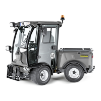
1 OFF: Ignition off
2 ON: Ignition on
3 GL: Pre-heat
4 ST: Start motor
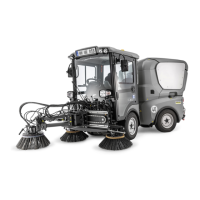
Quick couplings 1 and 2 are standard
equipment on all machines.
Quick coupling 3 (option) is connected to
the lift cylinders via a T-piece and is used
while the front lift is deactivated, e.g. to lift
a front loader.
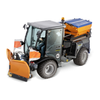
Front right quick couplings
Quick coupling 4 is standard equipment on
all machines.
Rear quick couplings
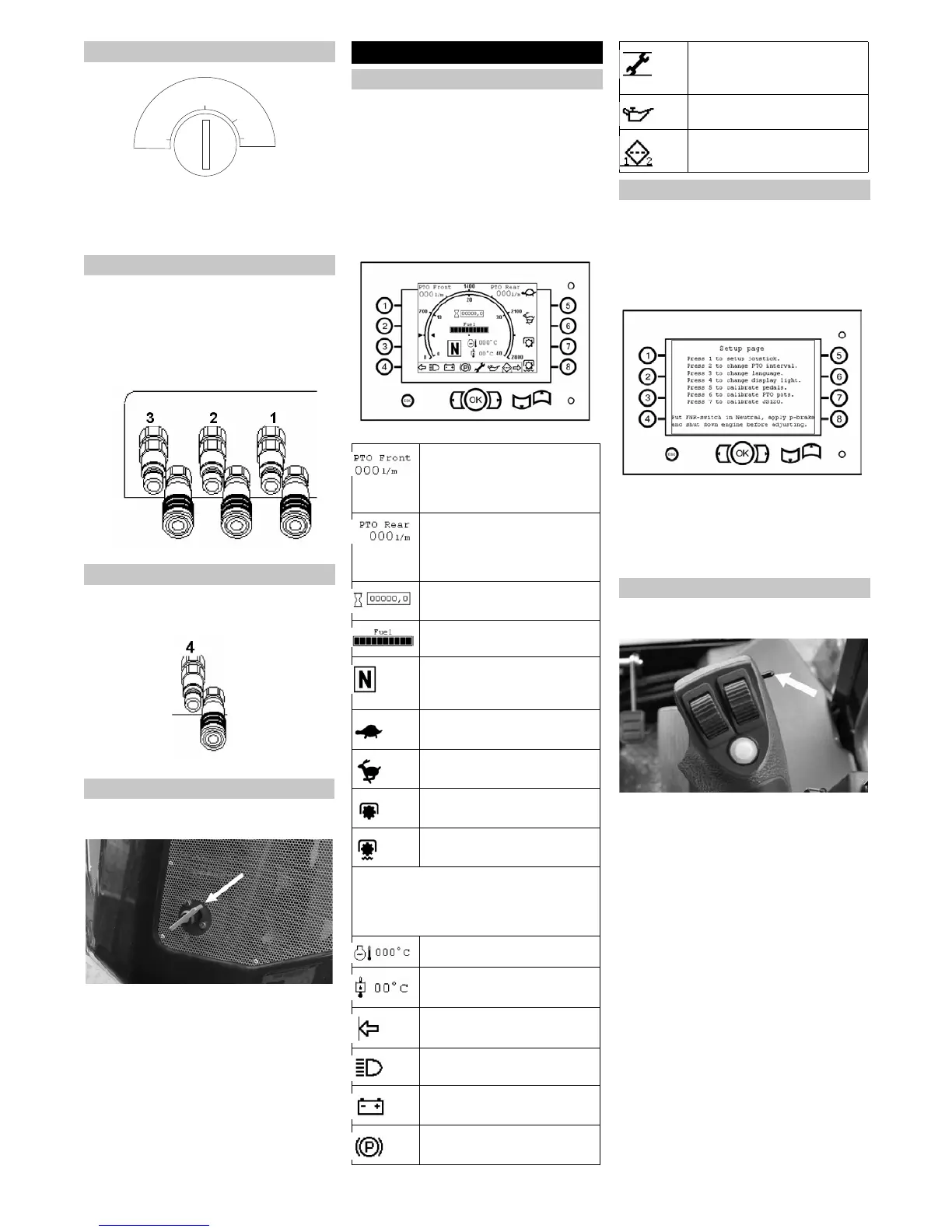
The main switch is located on the front side
of the rear machine portion.
Main switch, turned off position
The main switch must be turned on to
operate the machine. If the machine is
shut off and not started back up imme-
diately, switch the main switch off and
remove it.
The machine is fitted with a display or oper-
ating panel:
– The display and the indicator lamps are
located in the interior.
The outer ring displays the motor speed
up to 2,000 rpm/min, the inside ring is
the odometer, it displays a max. speed
of 40 km/h.
– The outer area includes buttons and
keys for setup functions.
Operating panel/display
몇 WARNING
Changes to the setup can influence the en-
tire machine and become traffic hazard.
Therefore: Only perform safety-relevant
adjustments for calibration after having
consulted customer service.
Press the OK button when the machine
is running.
Press buttons 1-7 to proceed through
the menu.
Press the ESC key during navigation to
return to the previous menu.
The multi-function lever is equipped with a
switch to select the travel direction.
FORWARD: Switch to the front, the
FORWARD travel direction is activated
and the drive direction indicator (F)
lights up on the display.
REVERSE: Switch to the rear, the RE-
VERSE travel direction is activated and
the drive direction indicator (R) lights up
on the display.
NEUTRAL: The switch position is in the
centre, (N) will light up on the display.
Ignition
Front hydraulic connection
Rear hydraulic connection
Main switch
OFF
ON
GL
ST
Operations
Operating panel/display
Feed volume, front work hy-
draulics
Note: The feed volume is ad-
justed via potentiometer B.
Feed volume, rear work hy-
draulics
Note: The feed volume is ad-
justed via potentiometer C.
Operating hour counter
Tank indicator
Travel direction indicator: For-
ward (F), reverse (R) or neu-
tral (N)
Slow transport range
Fast transport range
Work range 1 (cruise control)
Work range 2 (limit load con-
trol)
Warning signals
The warning indicators only illuminate
when important information needs to be
displayed.
Cool water temperature
Temperature of hydraulic oil
Travel direction indicator
Driving light (dipped head-
lights)
Battery control display
Parking brake
Service display: lights up if the
respective service work needs
to be performed
Oil pressure display
Filter: lights up if filter 1 or filter
2 is obstructed
Setup menu
Driving direction selector switch
22 EN
 Loading...