- 6
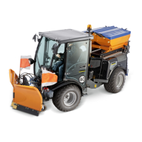
Control of rear hydraulic connection 4
Operation of a snow shield and sand
spreader.
Move the joystick into X direction or use
the left rolling switch.
Note: Float position not possible in this
function.
Control of front hydraulic connection 3
Use the right rolling switch.
Note: Float position not possible in this
function.
Control of front hydraulic connection 2
Press and hold the button, move the
joystick into Y direction.
For float position: Press and hold the
button, move the joystick to the front
and then back into the 0 position.
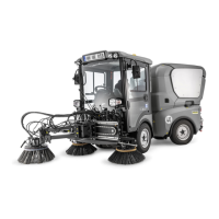
Control of rear hydraulic connection 4
Operation of mower decks with two side
panels.
Use the left rolling switch.
For float position: Press and hold the
button, move the joystick to the right
and then back into the 0 position.
Control of front hydraulic connection 3
Use the right rolling switch.
For float position: Move the right rolling
switch forward and then back into the 0
position.
Control of front hydraulic connection 2
Press and hold the button, move the
joystick into Y direction.
For float position: Press and hold the
button, move the joystick to the front
and then back into the 0 position.
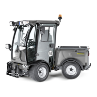
Control of rear hydraulic connection 4
To control a front loader (or another func-
tion with the front lift deactivated).
Move the joystick into Y direction.
For float position: Press and hold the
button, move the joystick to the front
and then back into the 0 position.
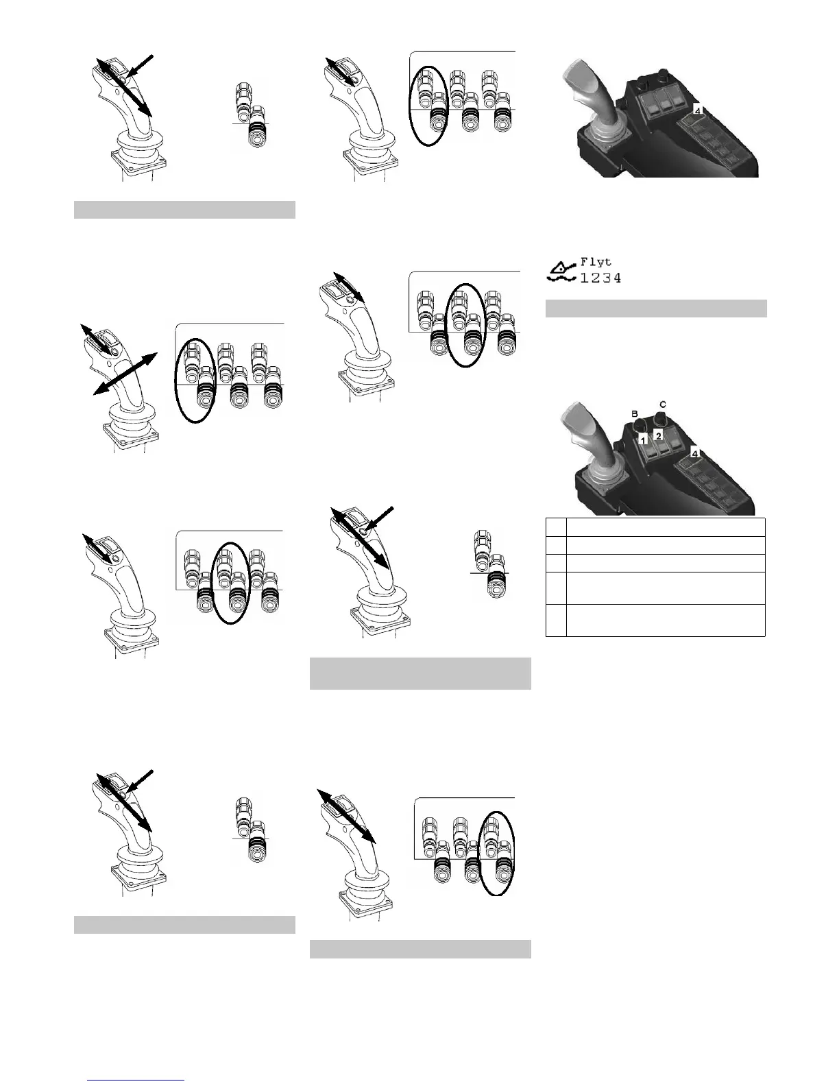
Control of front hydraulic connection 1
Actuate switch no. 4; the float position is
activated.
Note: If the respective function is in float
position, the display will show the respec-
tive symbol with the numbers 1 through 4.
The hydraulic connections are numbered
as shown.
The work hydraulics of the machine have a
stepless variable feed volume of 0 to 120 l/
min. This allows the greatest flexibility
when selecting attachments.
Ensure that the attachment is connect-
ed properly.
Read the attachment's operating in-
structions and find out what feed vol-
ume to use for the attachment.
Start the machine, see "Starting the
motor".
Activate the float position via the switch.
IMPORTANT: Rotate potentiometers B
and C anti-clockwise into the 0 position.
Press the front or rear switch for the
work hydraulics (depending on the con-
nected attachment).
Note: If the front and rear attachments
are used simultaneously, you can only
select a feed volume of 0 - 60 l/min
each. If a feed volume of 0 - 120 l/min is
required, you can only use one attach-
ment, either in the front or in the rear.
Three selections will be shown on the
display or the operating panel:
0 - 60 l/min front and rear
0 - 120 l/min front
0 - 120 l/min rear
Select the desired place of removal/
feed volume via the buttons 1 through
3.
Description - programme 2
Description - programme 3
Independent of the set up
programme
Float position
Operating the work hydraulics
1 Front work hydraulics
2 Rear work hydraulics
4 Float position
B Potentiometer for the front work hy-
draulics (feed volume)
C Potentiometer for the rear work hy-
draulics (feed volume)
24 EN
 Loading...