7-14 Triggering Model 6485 Picoammeter Instruction Manual
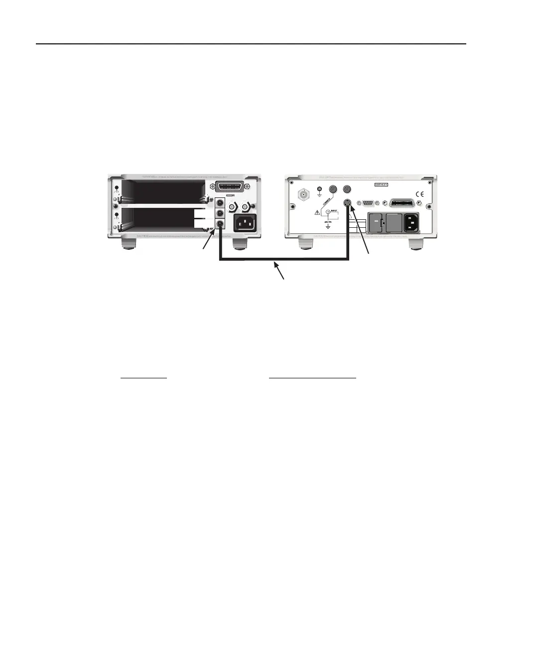
The trigger link connections for this test system are shown in Figure 7-8. The trigger link
of Model 6485 is connected to the trigger link (IN or OUT) of the switching mainframe.
Note that with the default trigger settings of the switching mainframe line #1 is an input
and line #2 is an output.
Figure 7-8
Trigger link connections
For this example, Model 6485 and switching mainframe are configured as follows:
To store readings in Model 6485 buffer, first set the number of points to store in the buffer:
1. Press CONFIG and then STORE.
2. Set the buffer size to 10 using the and range keys and the and cursor
keys.
3. Press ENTER.
4. The next time STORE is pressed, the asterisk (*) annunciator turns on to indicate
the buffer is enabled (See Section 6 for details on buffer operation).
Model 6485 Switching Mainframe
Factory Defaults Restored Factory Defaults Restored
Trig-In Event = TLink Scan List = 1!1-1!10
Trigger Input Line = #2 Number of Scans 1
Trigger Output Line = #1 Channel Spacing = TrigLink
Trigger Output Event = ON
Trigger Count = 10
Trigger Delay = Auto
MADE IN USA
7001 or 7002 Switch System
Model 6485 Picoammeter
OUT
IN
Trigger
Link
Trigger
Link
120
FUSE LINE
630mA
LINE RATING
50, 60Hz
30 VA
T
(SB)
100 VAC
120 VAC
315mAT
(SB)
220 VAC
240 VAC
!
INPUT
(CHANGE IEEE ADDRESS
WITH FRONT PANEL MENU)
IEEE-488
CAT I
TRIGGER LINK
RS-232
MADE IN
U.S.A.
220V PK
ANALOG OUT
Trigger
Link Cable
(8501)