I-20 Applications Guide Model 6485 Picoammeter Instruction Manual
The basic configuration for measuring high resistance using the 6485 Picoammeter is
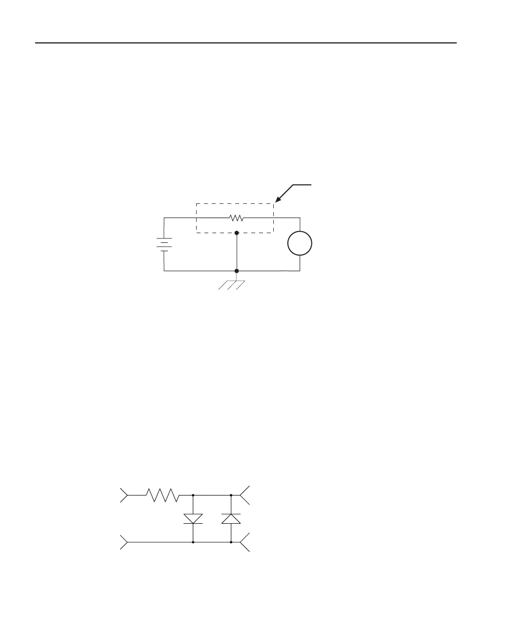
shown in Figure I-16. The HI terminal of the 6485 is connected to one end of the unknown
resistance (R) and the HI of the voltage source to the other end of the resistance. The LO
terminal of the 6485 is connected to the LO terminal of the voltage source. Both LO termi-
nals are also connected to earth ground. This should be done via the ground link on the
rear of the 6485.
Figure I-16
Measuring High Resistance Using the 6485
To prevent generated current due to electrostatic interference, place the unknown resis-
tance in a shielded test fixture. The metal shield is connected to the LO terminal of the
6485.
If the voltage source is greater than 220V, a current limiting resistor in series with the 6485
HI terminal as well as protection diodes (IN 3595) across the meter input should be used
to prevent damage to the 6485 in the event the unknown resistance breaks down and
becomes shorted. The diodes should be in a light-tight enclosure to prevent light induced
leakage, A diagram of the overload protection circuit is shown in Figure I-17.
Figure I-17
Overload Protection Circuit for 6485 Picoammeter
Programmable
V-Source
(V)
A
+
-
6485
Picoammeter
Unknown Resistance
(R)
Measured
Current
Metal
Shield
HI
LO
HI
LO
Equivalent Circuit
HI
LO
To 6485 Input
R
IN 3595