9-18 Remote Operation Model 6485 Picoammeter Instruction Manual
RS-232 connections
The RS-232 serial port can be connected to the serial port of a controller (i.e., personal
computer) using a straight through RS-232 cable terminated with DB-9 connectors. Do
not use a null modem cable. The serial port uses the transmit (TXD), receive (RXD), and
signal ground (GND) lines of the RS-232 standard. It does not use the hardware handshak-
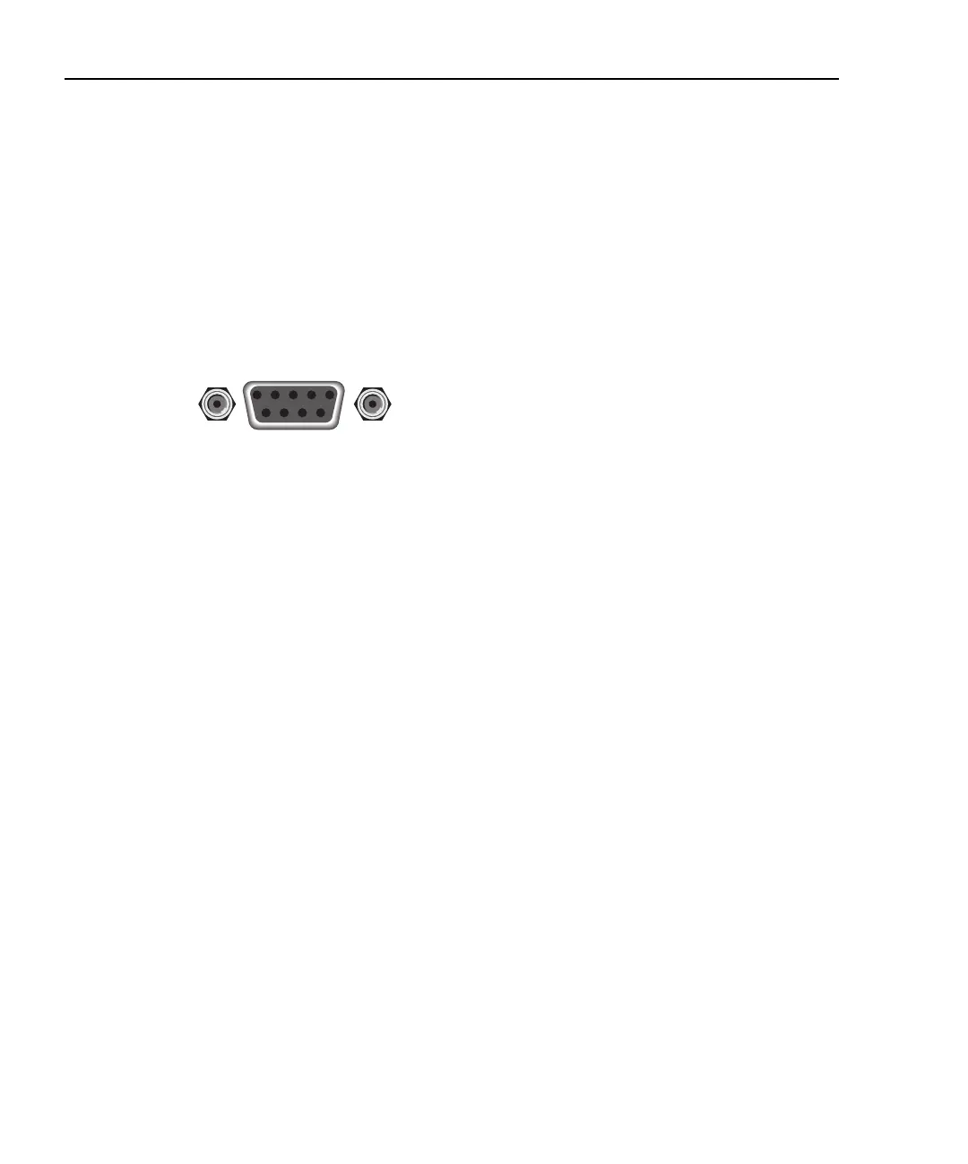
ing lines CTS and RTS. Figure 9-4 shows the rear panel connector for the RS-232 inter-
face, and Table 9-2 shows the pinout for the connector.
Figure 9-4
RS-232 interface connector
If your computer uses a DB-25 connector for the RS-232 interface, you will need a cable
or adapter with a DB-25 connector on one end and a DB-9 connector on the other, wired
straight through (not null modem). Table 9-3 provides pinout identification for the 9-pin
(DB-9) or 25-pin (DB-25) serial port connector on the computer (PC).
9876
54321
Rear Panel Connector
RS232