Model 6485 Picoammeter Instruction Manual Getting Started 1-9
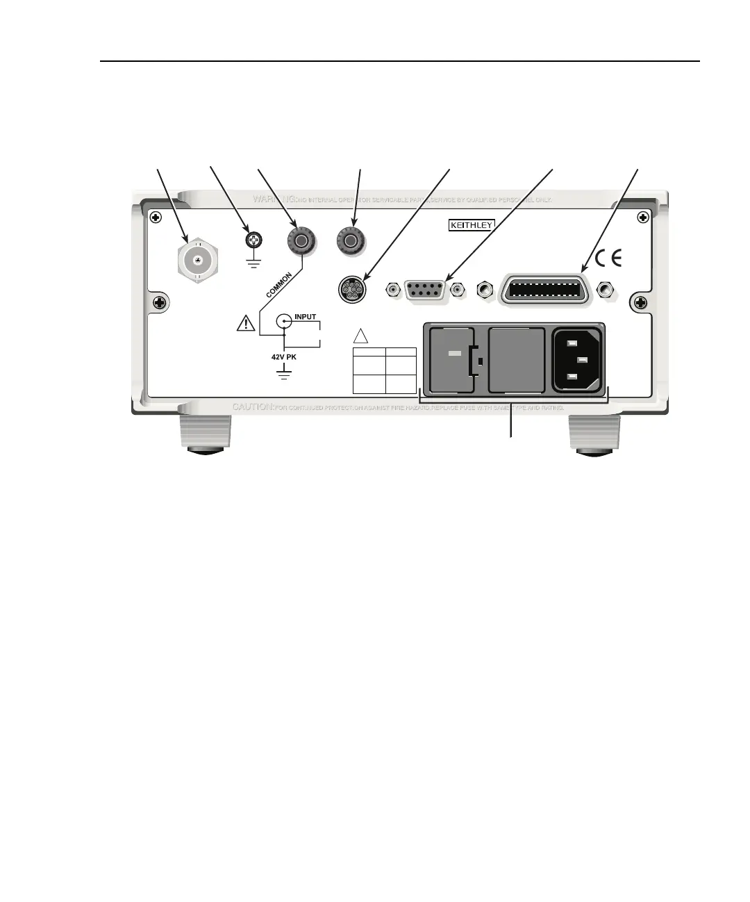
Figure 1-2
Rear panel
1 INPUT
This standard female BNC connector is used to connect the signal to be measured to the input of the
Model 6485. Mates to a BNC cable.
2 CHASSIS
This screw terminal is used to connect COMMON to CHASSIS ground via the ground link connector.
3 COMMON
This standard banana connector can be used as input LO or as the common for the ANALOG OUT.
Also can be used as a ground link.
4 ANALOG OUT
This standard banana connector provides a scaled, inverting output (inverting 2V full scale on all
ranges).
5 TRIGGER LINK
Eight-pin micro-DIN connector for sending and receiving trigger pulses among connected instru-
ments. Use a trigger link cable or adapter, such as Models 8501-1, 8501-2, 8502 and 8503.
120
FUSE LINE
630mA
LINE RATING
50, 60Hz
30 VA
T
(SB)
100 VAC
120 VAC
315mAT
(SB)
220 VAC
240 VAC
!
INPUT
(CHANGE IEEE ADDRESS
WITH FRONT PANEL MENU)
IEEE-488
CAT I
TRIGGER LINK
RS-232
MADE IN
U.S.A.
220V PK
ANALOG OUT
13 45 67
8
2