I-22 Applications Guide Model 6485 Picoammeter Instruction Manual
Surface insulation resistance (SIR)
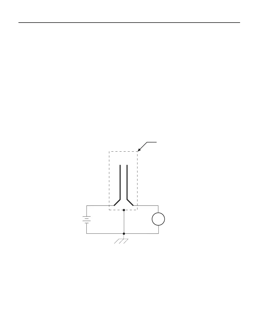
Figure I-19 shows how to measure the insulation resistance between PC board traces. Note
that the drawing shows a "Y" test pattern for the measurement. This is a typical test pattern
for SIR tests.
A bias voltage (typically 50V) is applied to the test pattern for a specified time (typically
one second) to polarize the test pattern. The test voltage (typically 100V) is then applied
and, after a specified time (typically one second), Model 6485 measures the current. Sur-
face insulation resistance can now be calculated as follows:
where: V is the sourced test voltage
I is the measured current
Figure I-19
Connections; surface insulation resistance test
Photodiode characterization prior to dicing
The Model 6485 can be used as part of a cost-effective semiconductor photodiode leakage
test system. This test characterizes the photo current under various illumination condi-
tions.
In addition to the Model 6485, specialized equipment is required. This equipment includes
a calibrated optical source in addition to semiconductor equipment (probe card or needle
SIR
V
I
----=
A
+
-
HI
LO
HI
LO
PC Board
Test Pattern
Programmable
V-Source
(V)
6485
Picoammeter
Measured
Current
(I)
Metal
Shield
Equivalent Circuit