I-8 Applications Guide Model 6485 Picoammeter Instruction Manual
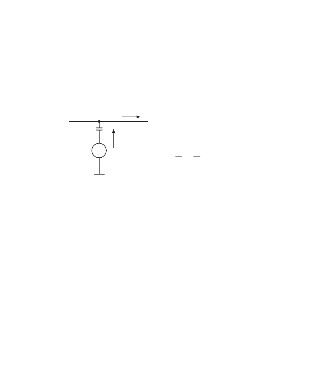
Figure I-4 shows an example of AC electrostatic coupling. An electrostatic voltage source
in the vicinity of a conductor, such as a cable or trace on a PC board, generates a current
proportional to the rate of change of the voltage and of the coupling capacitance. This cur-
rent can be calculated with the following equation:
Figure I-4
Electrostatic coupling
For example, two conductors, each with lcm
2
area and spaced lcm apart by air, will have
almost 0.1pF of capacitance. With a voltage difference of 100V and a vibration causing a
change of capacitance of 0.01pF/second (a 10% fluctuation), a current of 1pA will be gen-
erated.
To reduce the effects of the fields, a shield can be built to enclose the circuit being mea-
sured. The easiest type of shield to make is a simple metal box or meshed screen that
encloses the test circuit. Shielded boxes are also available commercially.
Figure I-5 illustrates an example of shielding. Made from a conductive material, the shield
is always connected to the low impedance input of the electrometer or picoammeter. If cir-
cuit low is floating above ground, observe special safety precautions to prevent anyone
from touching the shield. (See “Floating measurements,” page 2-12.)
iC
dV
d
-------
V
dC
dt
-------
+=
V
Coupling
capacitance
Electrostatic
voltage source
Ground-referenced
signal conductor
C
i
i = C + V
dV
dt
dC
dt