Model 6485 Picoammeter Instruction Manual Measurement Concepts 2-9
Input voltage overload (OVRVOLT message)
During normal operation, there should not be a significant voltage between the input HI
and LO terminals of the Model 6485. However, occasionally, as in the case of a DUT fail-
ure, a customer voltage source can become shorted directly to the Model 6485. Under that
condition, protection circuits within the 6485 will limit the current flow for higher current
ranges (20µA to 20mA). Additionally, when operating on the 2mA and 20mA ranges or
when the 6485 auto ranges up to these ranges as a response to the applied voltage, if the
input voltage exceeds 60V, the Model 6485 will change from a current limit to a 1MΩ−
3MΩ input impedance to prevent excess power dissipation. The OVRVOLT message will
be displayed to indicate the change in the protection circuit. The same information is avail-
able with remote operation (see “Measurement event status,” page 10-13.)
To return the instrument to normal operation, the over-voltage condition must be removed.
Once the input voltage is reduced to under 60V, the protection circuit will return to its cur-
rent limit operation until the current is reduced to a valid (on-scale) level. Extended opera-
tion near, but under 60V, will produce heat inside the instrument and may require time to
cool before returning to accurate readings.
Test fixture
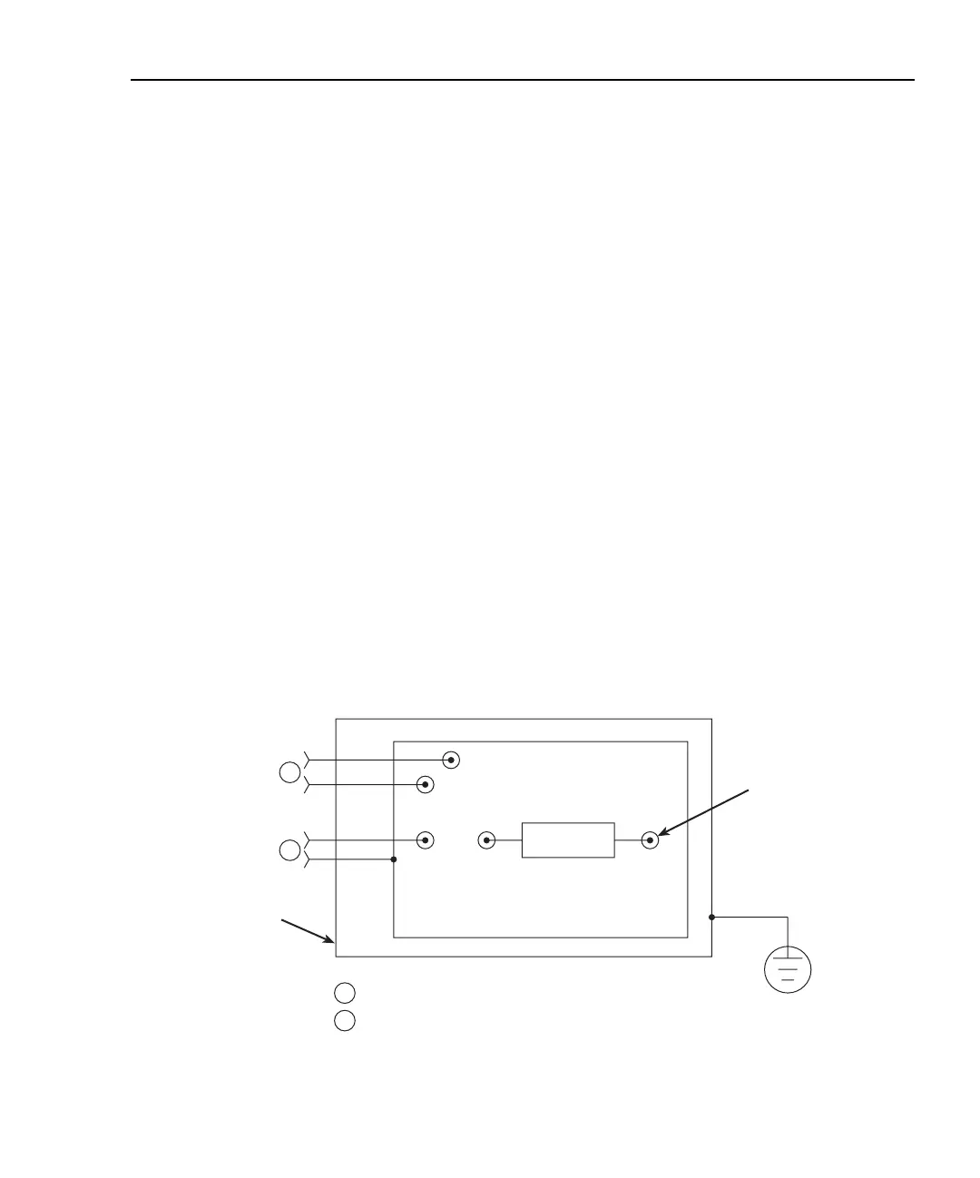
Whenever possible, use a shielded low leakage test fixture to make precision measure-
ments. A general purpose test fixture is shown in Figure 2-5. This test fixture will accom-
modate a variety of connection requirements.
Figure 2-5
General purpose test fixture
From External
Power Supply
To 6485
Input
Metal Guard Plate
Banana Jacks (typical, from external power supply)
Female BNC Input Connector (Model 6485)
Insulated
Terminal
Post
Safety
Earth
Ground
A
A
B
B
DUT
Metal Chassis