1-12 Getting Started Model 6485 Picoammeter Instruction Manual
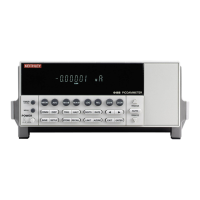
Display
Readings can be displayed in engineering units or scientific notation (see “Units,” page 4-
3 for details). Annunciators indicate various states of operation. See “Front panel sum-
mary,” page 1-6 for a complete listing of display annunciators.
The Display and Keys Test allows you to test display digit segments and annunciators, and
check the functionality of front panel keys. These tests are accessed through the MENU.
To access these tests:
1. While in reading mode, press MENU. If not in reading mode, press EXIT first then
press MENU.
2. Scroll using range keys ( or ) to the TEST sub-menu (TEST will be flashing).
3. Press ENTER (or ) to select TEST (DISP will be flashing).
4. Scroll using range keys ( or ) to desired test (DISPlay or KEY).
Refer to Section 13 for additional details.
Status and error messages
Status and error messages are displayed momentarily. During operation and programming,
you will encounter a number of front panel messages. Typical messages are either of status
or error variety, as listed in Appendix B.
Messages, both status and error, are held in queues. For information on retrieving mes-
sages from queues, see Section 10.
Power-up
Line power connection
Follow the procedure below to connect the Model 6485 to line power and turn on the
instrument.
1. Check to see that the line voltage indicated in the window of the fuse holder assem-
bly (Figure 1-2) is correct for the operating voltage in your area. If not, refer to the
procedure in Section 17 for setting line voltage and fuse replacement.
CAUTION Operating the instrument on an incorrect line voltage may cause dam-
age to the instrument, possibly voiding the warranty.
2. Before plugging in the power cord, make sure that the front panel power switch is
in the off (O) position.
3. Connect the female end of the supplied power cord to the AC receptacle on the rear
panel. Connect the other end of the power cord to a grounded AC outlet.

 Loading...