I-18 Applications Guide Model 6485 Picoammeter Instruction Manual
Applications
The following applications require an external voltage source.
NOTE External triggering and delay are covered in Section 7.
With the proper use of external triggering between Models 6485 and voltage source, the
tests can be automated. All of the applications require a bias time or delay, which can be
provided by the delay feature of Model 6485. When Model 6485 is triggered, a measure-
ment will not be performed until the delay period expires.
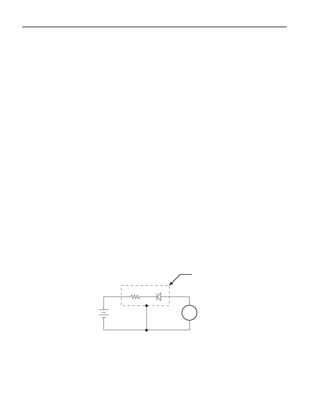
Diode leakage current
Figure I-14 shows how to measure the leakage current for a diode. By sourcing a positive
voltage, the leakage current through the diode will be measured. Note that if you source a
negative voltage, you will forward bias the diode. Resistor R is used to limit current in the
event that the diode shorts out or it becomes forward biased. Select a value of R that will
limit current to 20mA or less.
A profile for leakage current can be developed by measuring current at various voltage
levels. For example, program the voltage source to source from 1 to 10V in 1V steps. With
the proper use of external triggering, the Model 6485 performs a current measurement on
each voltage step. To ensure that the voltage is settled before each current measurement,
you can program Model 6485 for a delay. For example, if you program Model 6485 for a
one second delay, each measurement will be performed after the voltage step is allowed to
settle for one second. The current measurements can be stored in the buffer.
NOTE Buffer operation is covered in Section 6.
Figure I-14
Connections; diode leakage current test
A
+
-
Programmable
V-Source
6485
Picoammeter
Metal
Shield
HI
LO
HI
LO
R
Diode
Equivalent Circuit