I-24 Applications Guide Model 6485 Picoammeter Instruction Manual
Figure I-21
PIN photo diode leakage
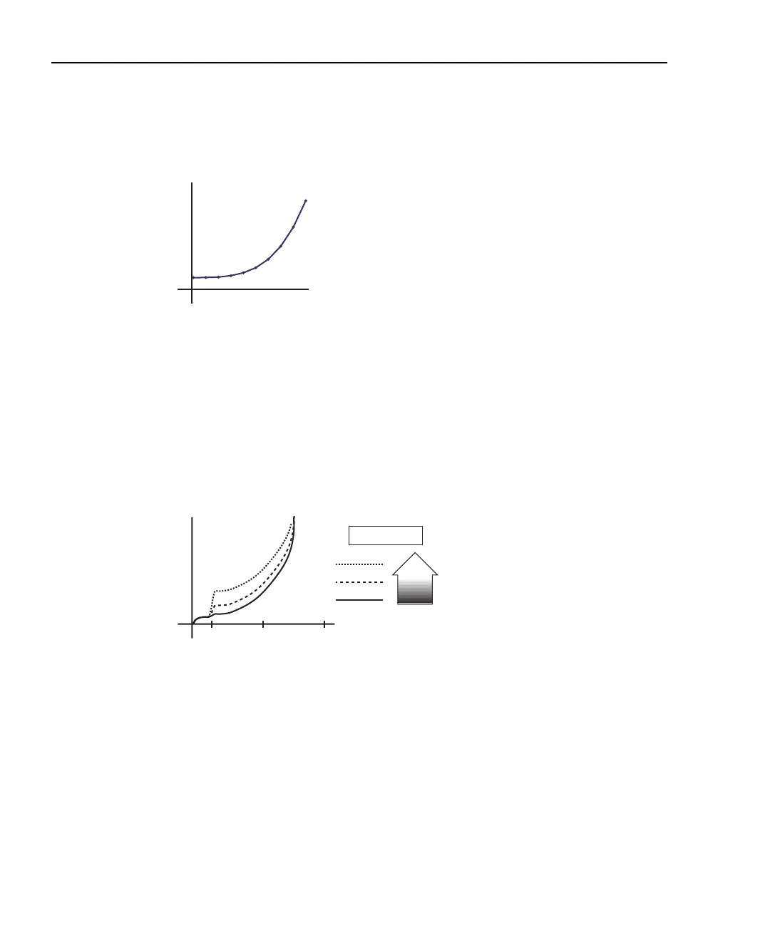
In total darkness, Avalanche diodes respond as shown by the solid line in Figure I-22.
Notice the small irregularity of the curve while sweeping around 10-12V. This irregularity
is made larger under additional applied light (see dashed lines of Figure I-22).
Figure I-22
Avalanche photo diode leakage
Connections are made to the Model 6485 through the BNC input connector (located on the
rear panel) (Figure I-23). In order to properly sequence voltage and measurement of leak-
age current, the instruments triggering needs to be linked. Trigger link connection to the
Model 2400 is made to the Model 6485 through the Trigger Link connector (located on the
rear panel).
I
V
05
P.I.N. photo diode
I
V
0
Avalanche photo diode
10 50 100
LEGEND
More
Light