EasyManuals Logo

Keithley 6485 User Manual

Keithley 6485
312 pages
To Next Page IconTo Next Page
To Previous Page IconTo Previous Page
Page #123 background imageLoading...
Page #123 background image
Model 6485 Picoammeter Instruction Manual Remote Operation 9-5
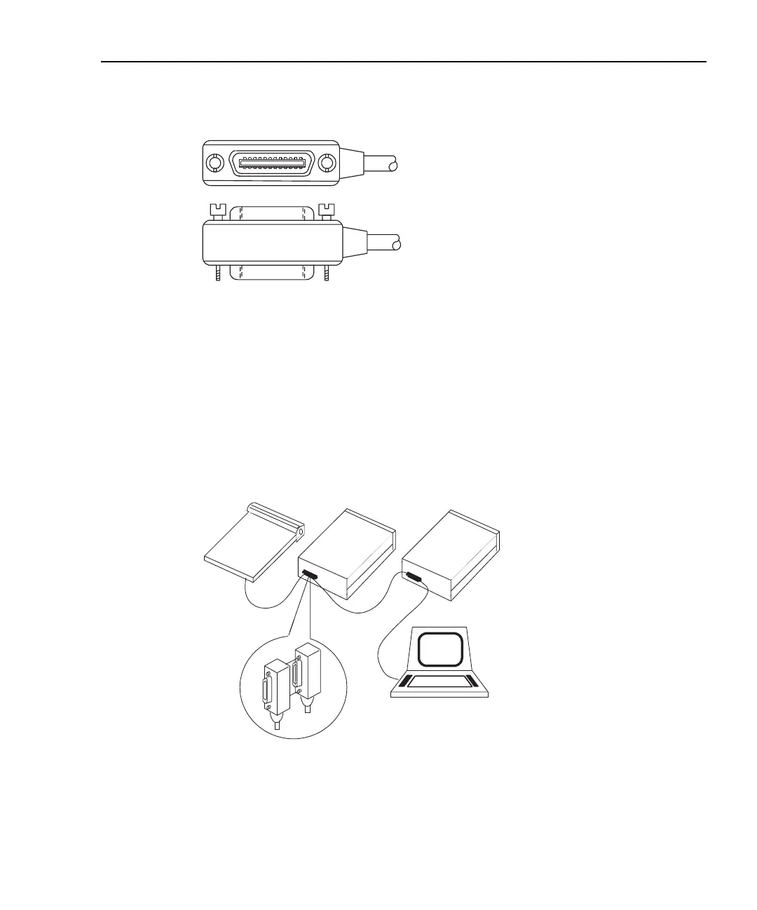
Figure 9-1
IEEE-488 connector
To allow many parallel connections to one instrument, stack the connector. Two screws are
located on each connector to ensure that connections remain secure. Current standards call
for metric threads, which are identied with dark-colored screws. Earlier versions had dif-
ferent screws, which were silver-colored. Do not use these types of connectors on Model
6485 because it is designed for metric threads.
Figure 9-2 shows a typical connecting scheme for a multiunit test system.
Figure 9-2
Multi-unit connections
To avoid possible mechanical damage, stack no more than three connectors on any one
unit.
Instrument
Controller
InstrumentInstrument

Table of Contents

Other manuals for Keithley 6485

Questions and Answers:

Question and Answer IconNeed help?

Do you have a question about the Keithley 6485 and is the answer not in the manual?

Keithley 6485 Specifications

General IconGeneral
ModelKeithley 6485
CategoryPicoammeter
Input Impedance>10^14 Ohms
Voltage Burden<200µV
Accuracy0.4% of reading
Voltage Source RangeNot Applicable
Voltage Source ResolutionNot Applicable
Voltage Source AccuracyNot Applicable
InterfaceIEEE-488
Power Requirements100V to 240V AC, 50/60Hz
Dimensions89 mm high x 214 mm wide x 369 mm deep (3.5 in x 8.4 in x 14.5 in)

Related product manuals