Model 6485 Picoammeter Instruction Manual Applications Guide I-21
In the case that the source is connected directly across the protection circuit, make sure the
series resistance (R) is chosen so the current through the diodes is limited to <100mA. If
the current through the unknown resistance must be measured with an accuracy greater
than 10pA, use the protective method outlined in “Voltages greater than 220V,” page 2-6.
Cable insulation resistance
NOTE For this test, Model 6485 uses the source voltage, measure current method to
determine resistance. Once a current measurement is performed, resistance can
be calculated.
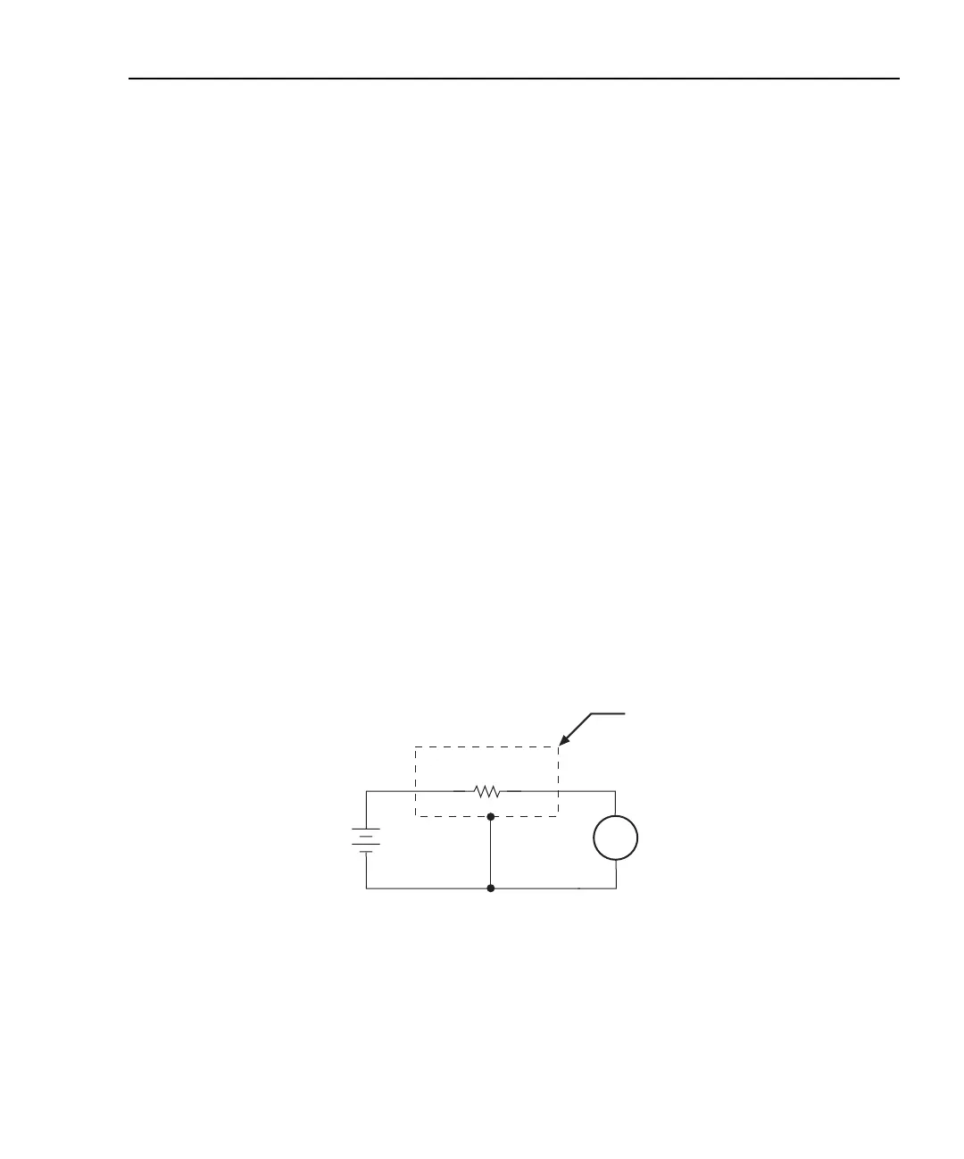
Figure I-18 shows how to measure the insulation resistance of a cable. The resistance of
the insulator between the shield and the inner conductor is being measured. The cable
sample should be kept as short as possible to minimize input capacitance to the picoam-
meter.
For this test a fixed bias voltage is applied across the insulator for a specified time to allow
the charging effects of cable capacitance to stabilize. The current is then measured. Cable
resistance (R) can then be calculated as follows:
where: V is the sourced bias voltage
I is the measured current
Figure I-18
Connections; cable insulation resistance test
R
V
I
----=
A
+
-
Programmable
V-Source
(V)
6485
Picoammeter
Measured
Current
(I)
Metal
Shield
HI
LO
HI
LO
Cable Resistance
(R)
Equivalent Circuit