Model 6485 Picoammeter Instruction Manual Applications Guide I-23
mounts, etc.,), as well as a triggerable voltage source (the Model 2400 is used in our exam-
ple). Several Model 6485's can be connected to probe pads to provide leakage current
readings forced by the bias voltage source. As an alternative, one or more 6485s could be
switched through a switching mainframe and matrix switch card arrangement to take cur-
rent measurements from multiple pads.
Measuring photo diode leakage can be described in two steps:
1. V
sweep
, I
meas
in total darkness
2. V
bias
, I
meas
in calibrated optical flux
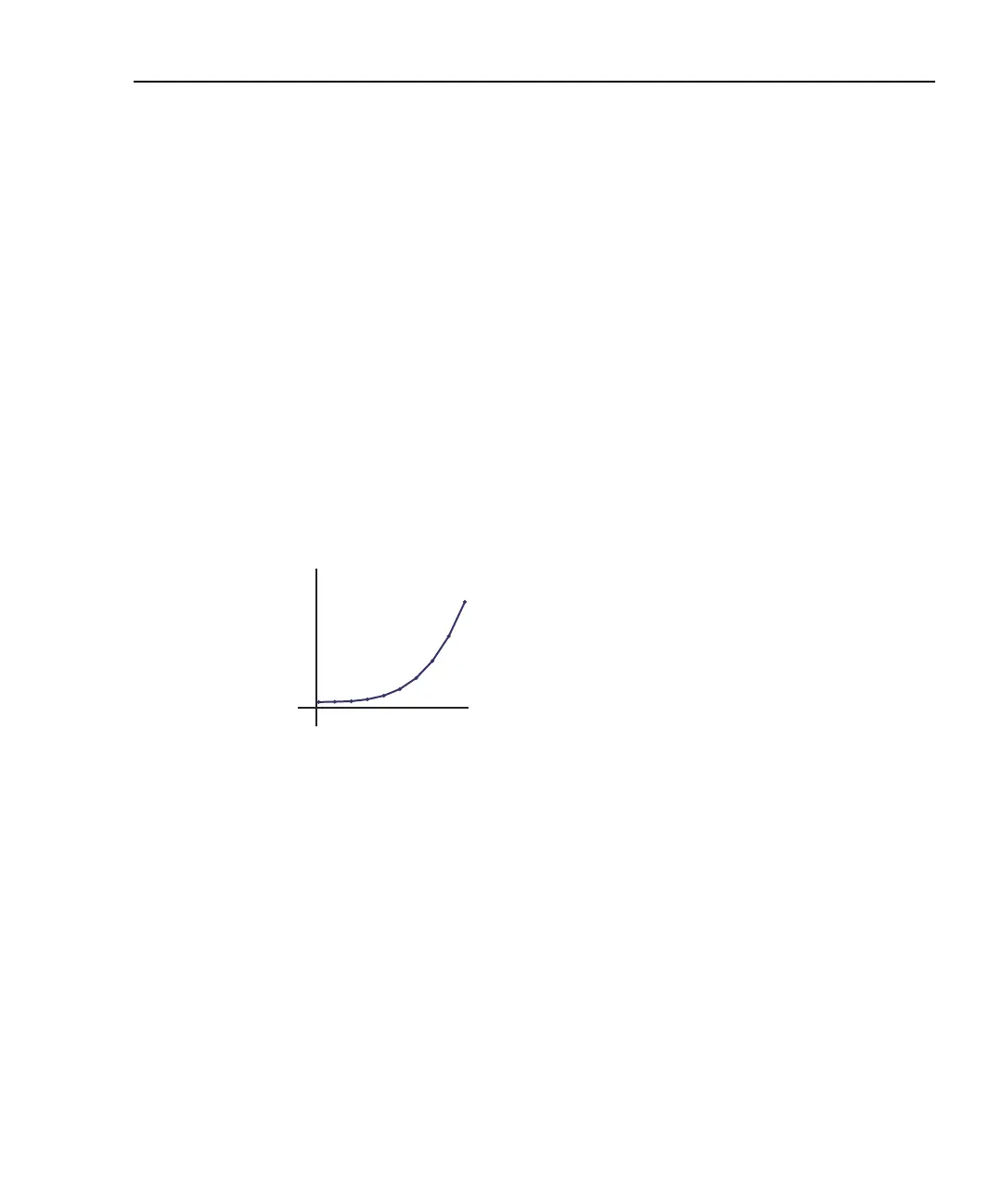
In the 1st step, voltage sweeps and the resulting current leakage is measured. Then, a bias
voltage is applied and resulting current leakage is measured while light is incrementally
increased in calibrated steps. The results produce a graph similar to Figure I-20.
Figure I-20
General photo diode leakage
P.I.N. (Positive Intrinsic Negative) diodes respond as shown in Figure I-21.
I
V
0
General photo diode