3-104 Keysight B1505A User’s Guide, Edition 12
Accessories
2. Low Sense
a. From N1254A Opt524 input connector
BNC connector. For connecting the BNC cable (B1512-61741) from the
Low Sense output connector of the N1254A-524. The BNC cable
(B1512-61741) is supplied with the N1275A.
b. To DUT output connector
BNC connector. This must be extended to the Emitter/Source terminal of a
DUT. For making connection, use a cable with BNC(m) connector,
manipulators, and such.
3. From B1505A
• Current Control MCSMU Force and Sense input connectors
Force and Sense triaxial connectors. For connecting 16494A triaxial cable
from an MCSMU in the B1505A mainframe.
This is used to drive a current control device.
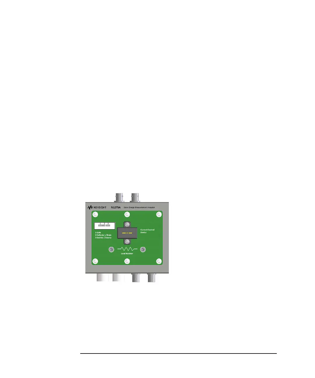
Figure 3-34 On-Wafer Gate Charge Measurement Adapter
To perform the gate charge measurement, a current control device or a load resistor
must be mounted on the socket or the studs.
The current control device must be a 3-pin inline package device which is expected
to have the same characteristics as DUT. If the device is not available, use a load
resistor. The resistor must satisfy the following specifications.
Resistance = Vr/Ir (Vr: rated voltage, Ir: rated current)
Peak power Vr × Ir × 1 ms