5-6 Keysight B1505A User’s Guide, Edition 12
Measurement Examples
Gate Charge Measurement
• “Packaged Device Testing Using Resistive Load on the N1259A-014 or
N1265A-014”
• “On-Wafer Auto-Testing Using Current Load Transistor on the N1274A”
• “On-Wafer Auto-Testing Using Resistive Load on the N1274A”
• “On-Wafer Auto-Testing Using Current Load Transistor on the N1275A”
• “On-Wafer Auto-Testing Using Resistive Load on the N1275A”
Packaged Device Testing Using Current Load Transistor
on the N1259A-014 or N1265A-014
Preparing Measurement Setup
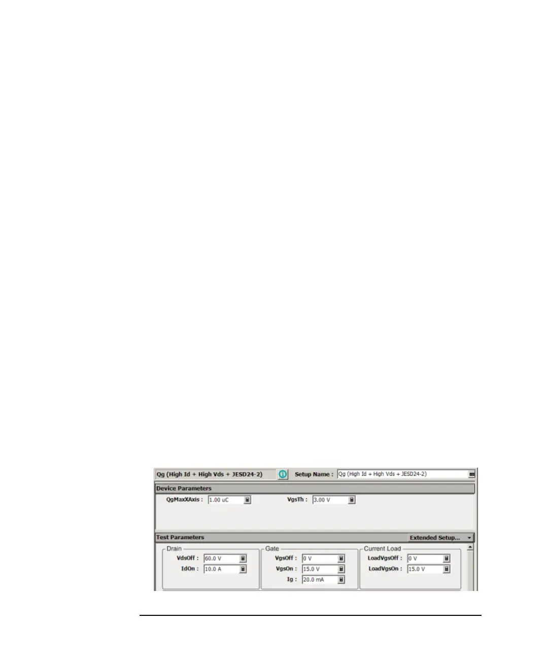
Used Application Test: Qg (High Id + High Vds+ JESD24-2)
1. Specify an approximate expected total gate charge value to the QgMaxXAxis
parameter and specify an expected threshold voltage to the VgsTh parameter.
2. Specify the Off voltage and On current to the VdsOff and IdOn parameters
according to your switching condition.
3. Specify the measurement range of the gate voltage using the VgsOff and VgsOn
parameters. If a resistor is directly connected to the DUT gate terminal in series
for preventing oscillation, specify the resistance value of the resistor to the
RgDUT parameter.
4. Specify the gate voltage range of the transistor for the current load using the
LoadVgsOff and LoadVgsOn parameters. For the LoadVgsOff parameter, specify
a gate voltage that the transistor is perfectly turned off. For the LoadVgsOn
parameter, specify a gate voltage that the transistor is perfectly turned on. Both
voltages should be within the maximum rating voltage of the transistor.