Unite
®
Panel System - Electrical Installation
Assembly Instructions
Assemble units as described herein only. To do otherwise
may result in instability. All screws, nuts and bolts must be
tightened securely and must be checked periodically after
assembly. Failure to assemble properly, or to secure parts
may result in assembly failure and personal injury.
27
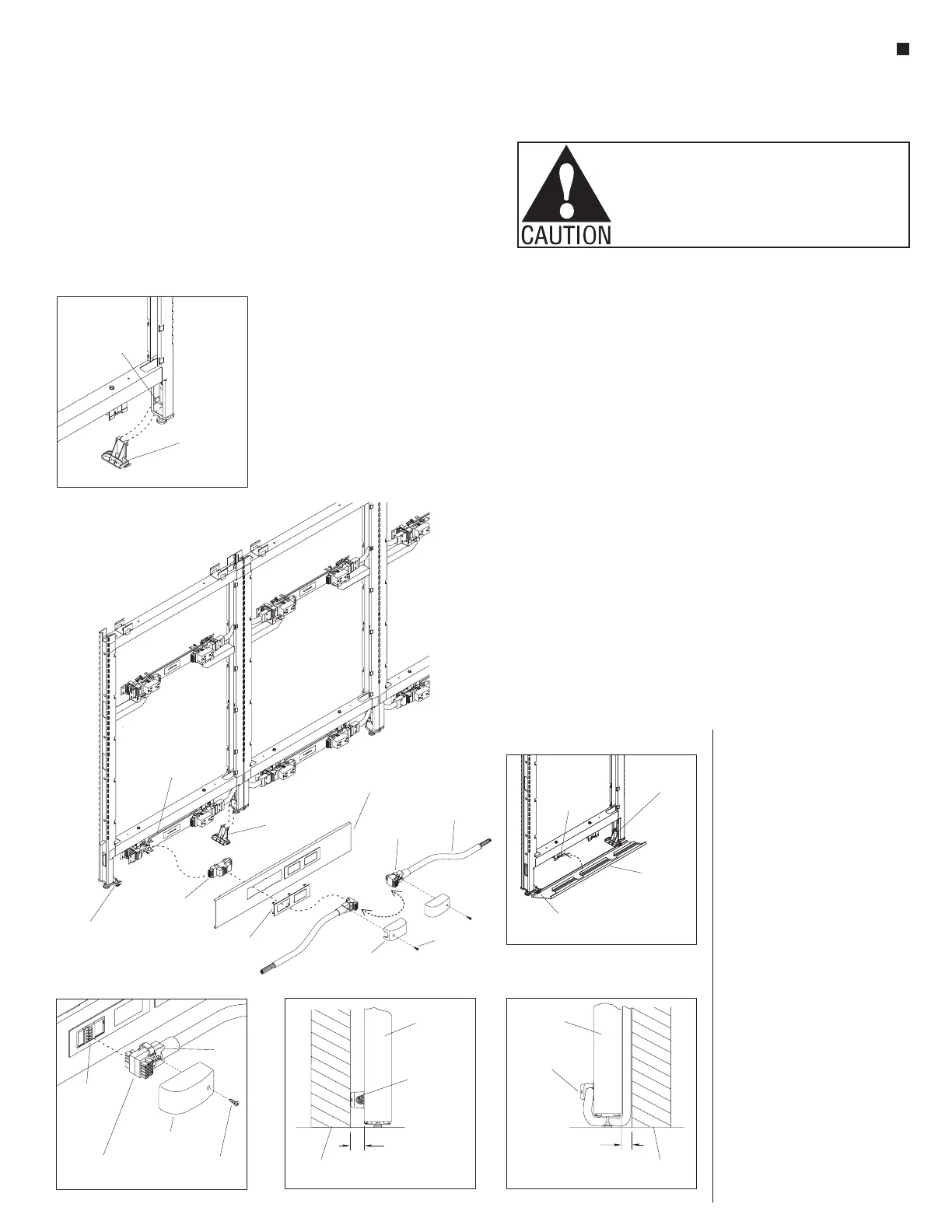
11-10-Wire Base Raceway Power Infeed
10-wire
rigid wireway
base raceway
hinge clip
base raceway
hinge clip
base infeed
adapter receptacle
base
raceway
trim
bezel plate
10-wire
base raceway
power infeed
base power
infeed shroud
shroud
screw
180°
lockbar
10-Wire Base Raceway Power
Infeed Installation
Note: All panel frames must
be mechanically connected
together, with all 10-wire rigid
wireways and panel-to-panel
power connections appropriately
installed before adding power
infeed, or connecting infeed to
power source.
1. At the bottom of the panel frame
which will receive 10-wire base
power infeed, install two plastic
base raceway hinge clips by
nesting the hooks of the clips into
the two slots in glide housing top,
then press down to snap hinge
clip into place (Figure 11
& Detail D).
2. Per the space-planning layout,
determine the location(s) for
base raceway power infeed.
Position the base infeed adapter
receptacle with the arrow at the
“N” facing up and slide into place
on the 10-wire rigid wireway in
the same manner as installing
a receptacle with the "10-Wire
Duplex Receptacle Installation"
instructions on page 26. Push the
base infeed adapter receptacle into
the wireway female connection
until the snap-clip on the wireway
captures the adapter, locking it
into place (Figure 11).
3. Snap the bezel plate into the base
raceway trim.
D
base raceway
hinge clip
glide
housing
E
wireway
mounting
bracket
“bump” of hinge clip
into “slot” of cover
base raceway
hinge clip
base
raceway
cover
G
1 /”min.
clearance
3
4
Unite
Panel
10-wire base
power infeed
building wall
H
Unite
Panel
10-wire base
power infeed
building wall
1 min.
clearance
”
4. Install the base raceway cover to
the power infeed panel by first
aligning the slots at the bottom
of the base raceway trim with the
bumps at the bottom of the base
raceway hinge clips. After both
ends are engaged to hinge clips
at the bottom, rotate the top of
the base raceway trim up toward
the frame and snap the top onto
the wireway mounting bracket to
secure (Figure 11 & Detail E).
5. Pull up the lock bar on the plug
end of the base raceway power
infeed. The base infeed can be
rotated 180° and installed in
one of two directions. Orient the
lock bar to be up, then press the
base raceway power infeed to the
adapter receptacle in the desired
direction. Press the lock bar
down to snap and secure the base
raceway power infeed onto the
base infeed adapter receptacle on
the power infeed, then place the
base infeed shroud over the infeed
and secure with the shroud screw
provided (Figure 11 & Detail F).
Note: The power infeeds are to
be connected to the power source
by a qualified electrician who
must follow all state and local
codes at the building site and
check the electrical integrity of the
finished system.
6. If a 10-wire base raceway power
infeed is located between a panel
and the building wall, the panels
must be located at least 1
3
/
4
” away
from the wall to provide adequate
clearance (Detail G). Alternately,
the 10-wire base power infeed
can be connected on the side
opposite the building wall, and
the conduit can be run under the
panel wall, and up between the
panel and building wall to be
connected to the power source.
This option requires a minimum
of 1” clearance between the panel
wall and the building wall for the
power infeed conduit to enter the
junction box on the wall
(Detail H).
base infeed
adapter
receptacle
base raceway
power infeed
shroud
screw
base power
infeed
shroud
lock
bar
 Loading...


