68
Assemble units as described herein only. To do otherwise
may result in instability. All screws, nuts and bolts must be
tightened securely and must be checked periodically after
assembly. Failure to assemble properly, or to secure parts
may result in assembly failure and personal injury.
Unite
®
Panel System - Stacking Sections Assembly
Assembly Instructions
Stacking Sections (aluminum
frame) Assembly
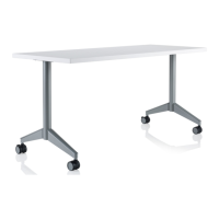
Important: Stacking sections
utilize vertical stacking posts with
“forks” that drop into the tops of
panel frames (after the top caps
are removed) and do not require
a fastener unless mounted at the
end-of-run (Figure 2).
Note: Once all vertical stacking
posts have been assembled to
the panel system, reference the
"Stacking Sections (aluminum
frame) Assembly" note at the end
of this page.
Stacking Sections (aluminum
frame) - Vertical Stacking Post
Intersection Assembly
1. Position a vertical stacking post
at the intersection as illustrated,
and press it into the cavity at
the top where the panel frame
and connector block meet. The
stacking post "fork" will rest
on top of the
3
/
8
-16 x 1
1
/
4
” bolt
attaching the connector block to
the frame. Post may be tapped
in place using a rubber mallet
(Figure 2).
Stacking Sections (aluminum
frame) - Vertical Stacking Post
In-Line Assembly
1. At a joined pair of panel frames,
position two vertical stacking
posts side-to-side as illustrated,
and press them into the cavity at
the top where two panel frames
meet. Posts may be tapped in
place one at a time using a rubber
mallet (Figure 2).
2. Secure the side-to-side vertical
stacking posts together using a
3
/
8
-16 x 1
1
/
4
” hex head bolt, two
washers and a
3
/
8
-16 k-lock nut
(Figure 2).
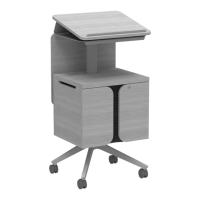
Stacking Sections (aluminum
frame) - Vertical Stacking Post
End-of-Run Assembly
1. To gain access inside of the
end-of-run panel frame, remove
the end-of-run panel tile by lifting
it up to disengage it from the
P-slots in the vertical post. Set
Figure 2-Stacking Sections (aluminum frame) - Corner &
In-Line Vertical Stacking Post Assembly
connector
block
vertical
stacking post
(corner intersection)
vertical
stacking post
(in-line)
31
/ -16 x 1 /
bolt
84
”
washer
3
/ -16
k-lock nut
8
panel frame
(corner
intersection)
3-Stacking Sections (aluminum frame) -
End-of-Run Vertical Stacking Post Assembly
vertical stacking
post (end-of-r
33
/ -16 x /
bolt
84
”
3
/ -16
k-lock nut
8
panel tile
(end-of-run)
panel frame
(end-of-run)
3
/ -16
k-lock nut
8
/ -16 x /
bolt
”
end-of-run
trim clip
panel tile aside until instructed
to assemble back onto the panel
frame (Figure 3).
Note: End-of-run trim clips
must be installed to end-of-run
vertical stacking posts to hold
vertical trim in place and must be
installed prior to installing tiles.
1. Attach end-of run trim clips to
the upper and lower mounting
locations on the end-of-run
vertical post using a
3
/
8
-16 x
3
/
4
”
hex head bolt and
3
/
8
-16 k-lock
nut (Figure 3).
2 For the “end-of-run panel frame,”
the uppermost end-of-run clip
must be removed and re-installed
one hole location below the top
mounting hole. This is so the
“fork” of the stacking section can
install to the end of the panel
frame. Loosely insert a
3
/
8
-16 x
3
/
4
” hex head bolt to the
top mounting hole of the end
panel frame (where the top
end-of-run trim clip was), then
twist on a
3
/
8
-16 k-lock nut.
Note: The nut must be positioned
inside the panel frame and flat
washer is not required. Next,
place a vertical stacking post
at end of the panel frame as
illustrated, with the notch of the
stacking post fork resting on the
threads of the
3
/
8
-16 x
3
/
4
” bolt.
Tighten the hex bolt and k-lock
nut to secure (Figure 3).
Stacking Sections (aluminum
frame) Assembly (cont.)
Note: If panel intersections do
not require a full-height light
shield and full-height vertical
intersection trim, reference
"Stacking Sections (aluminum
frame) - Intersection Kit
Assembly" instructions on
page 69. If panel intersections are
to be installed with a full-height
light shield and full-height vertical
intersection trim, reference
"Stacking Sections (aluminum
frame) - Full-Height Intersection
Assembly instructions on
page 70."
Rare Earth Magnets used with this product. The magnets can
be harmful to pacemaker wearers and others with medical
devices. Pacemaker wearers should stay at least one
foot away from the steel tiles.