60
Unite
®
Panel System - Trim Installation
Assembly Instructions
Assemble units as described herein only. To do otherwise
may result in instability. All screws, nuts and bolts must be
tightened securely and must be checked periodically after
assembly. Failure to assemble properly, or to secure parts
may result in assembly failure and personal injury.
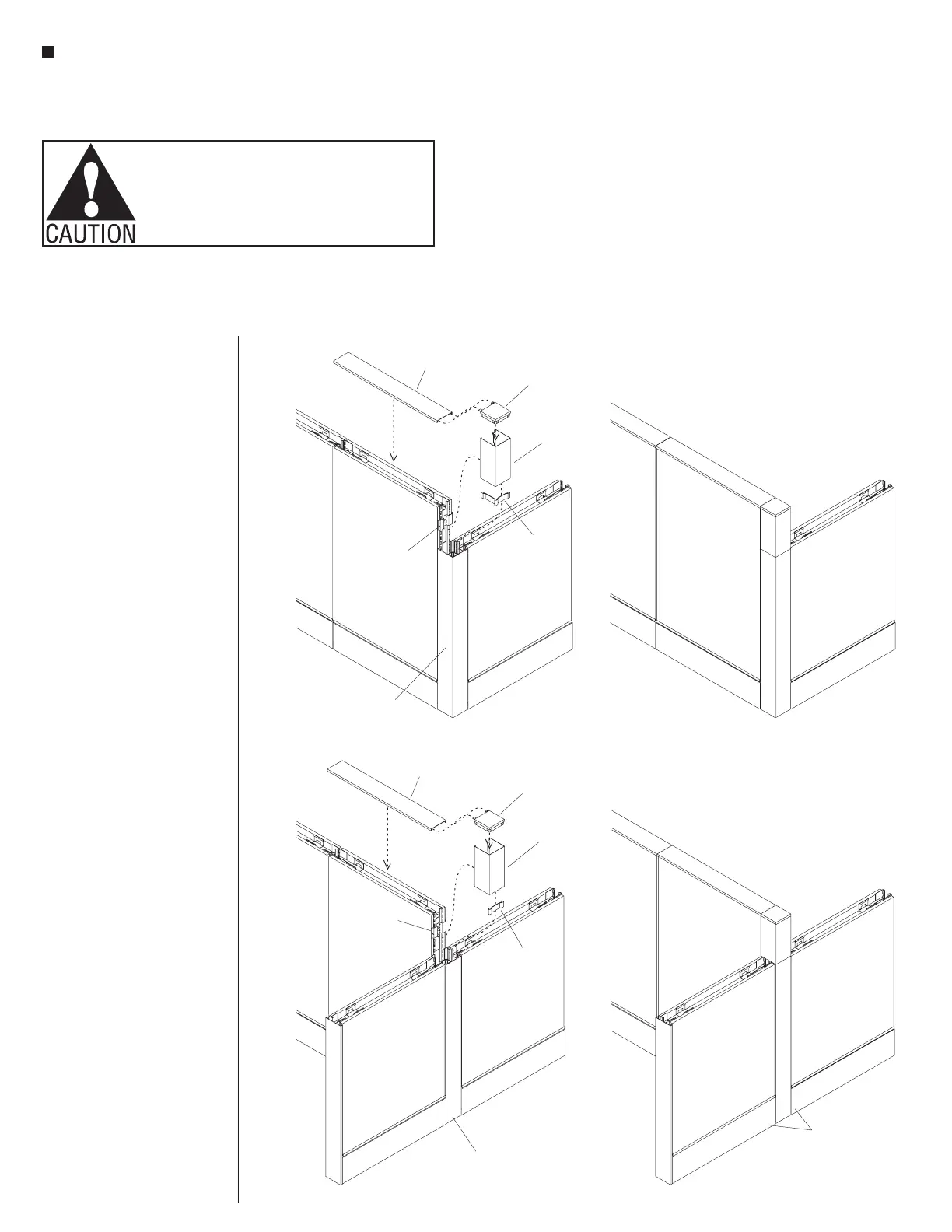
End-of-Run Change-of-Height
Trim Installation
Note: Vertical change-of-height
“snap-on” trim (in-line, 90° &
120°) is installed different than
“hang-on” intersection/end-of-
run trim. Change-of-height trim
snaps onto “end-of-run trim
clips” and has a specific top
and bottom, so requires correct
orientation to attach properly.
1. Install a vertical splice clip into
the top of the vertical 90° or
in-line corner intersection trim
(Figures 7 & 8).
Note: Vertical splice clips help
align mating vertical trim. The
splice clip is provided for various
in-line and 90° connections. For
in-line connections (Figure 8),
snap off one-half of the splice
clip at the notch location and
discard the unused section.
2. Orient the appropriate
“end-of-run change-of-height
trim” with the top up, so it
aligns properly with the installed
end-of-run trim clip. Correctly
positioned, the longer tabs of the
trim will be to the top, and the
smaller tabs with paint-hanging
hole will be at the bottom. The
bottom of the upper tabs will rest
on the top edge of the end-of-run
trim clip (Figures 7 & 8).
3. Hook one side of the end-of-run
change-of-height trim onto the
end-of-run trim clip. Rotate the
hooked trim towards the
un-clipped side, up against
the trim clip and snap the trim
into place by striking the loose
side with a rubber mallet or the
palm of your hand. Ensure that
the clip(s) are fully engaged
to prevent trim from falling off
(Figures 7 & 8).
4. Finally, orient the “dead end
intersection cap” as illustrated
and insert the tabs of the cap into
the narrow slots in the top cap.
Mate the dead-end intersection
cap into the top of the end-of-run
change-of-height trim and snap
the top cap into place at the top of
the panel frame (Figures 7 & 8).
top cap
end-of-run
trim clip
dead end
intersection cap
end-of-run
change-of-height
trim
vertical 90 corner
intersection trim
°
vertical 90°
splice clip
90°
change-of-height
panel
Figure 7 - End-of-Run 90° Change-of-Height Vertical Trim
end-of-run
trim clip
end-of-run
change-of
trim
vertical in-line
intersection trim
vertical in-line
splice clip
top cap
dead end
intersection cap
Figure 8 - End-of-Run In-Line Change-of-Height Vertical Trim
in-line
change-of-height
panels