74
Assemble units as described herein only. To do otherwise
may result in instability. All screws, nuts and bolts must be
tightened securely and must be checked periodically after
assembly. Failure to assemble properly, or to secure parts
may result in assembly failure and personal injury.
Unite
®
Panel System - Stacking Sections Assembly
Assembly Instructions
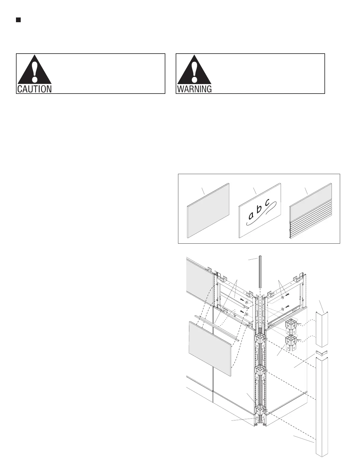
connector
block
light
shield
Figure 10 - Stacking Sections (steel frame) - Intersection
light
shield
lower intersection
trim (existing)
upper
trim
vertical 90
splice clip
°
33
/ -16 x /
bolt & washer
8
4
”
connector
block
stacking
section tile
stacking
trim rails
stacking section
tile (fabric)
stacking section
tile (markerboard)
F-Stacking Section (steel frame) - Tiles
stacking section
tile (slat wall)
fabric
Stacking Sections (steel
frame) - Intersection Kit
Assembly
Note: Intersection kits consists
of a 48" light shield, vertical
intersection trim, vertical 90°
splice clip, four
3
/
8
-16 x 1
1
/
4
” hex
head bolts, four washers and two
connector blocks.
1. Loosely attach two connector
blocks to one stacking panel
frame post at intersection. Use a
3
/
8
-16 x 1
1
/
4
” hex head bolt and
large flat washer to attach one
connector block to the lowest
mounting hole in the post and one
to the highest mounting location
(Figure 10).
2. Loosely attach the second
stacking section post to the two
connector blocks on the first post
using
3
/
8
-16 x 1
1
/
4
”hex head bolts
and large flat washers (Figure 10).
3. Tighten all
3
/
8
-16 x 1
1
/
4
” hex
bolts securing stacking section
posts to connector blocks at the
intersection (Figure 10).
Note: The light shields provided
with the intersection kits are only
available in 48” and will require
cutting. Light shields must be
installed after connector blocks
are assembled and all bolts are
tightened into connector blocks.
5. Cut the 48" light shield to
match the height of the stacking
section. Using the cut light shield,
position the bottom of the shield
at the top of the pre-existing light
shield. Snap the light shield into
the corner of each connector
block such that you hear a “click”,
ensuring that the light shield is
snug at each connector block
(Figure 10).
Stacking Sections (steel
frame) - Tile Assembly
Note: Tiles must be installed to
stacking section posts after all
panel components and exterior
tiles are installed to lower panel
frames. Re-install all lower panel
frame tiles that were removed from
previous steps before proceeding.
Note: Three-sided steel-
construction stacking sections (steel
frame) utilize exterior-mounted tiles
of either fabric, markerboard or slat
wall option (Detail F, page 74).
1. Stacking trim rails must fit between
the top of the lower panel tile and
the bottom of the stacking section
tile. Install two trim rails; one on
each side of the panel. Ensure the
large flange is oriented toward the
center of the panel.
2. If the stacking section tile is fabric
or slat wall, hold the tile up, then
center and nest the bottom of the
tile into the bottom of the stacking
trim rail. Push the top of the tile
against the frame and lift such that
the tabs of the stiffeners enter the
P-slots. Push in and gently allow
tile to nest down into the bottom
trim channel (Figure 10).
Note: Assembly of all standard
markerboard tiles are different than
standard fabric tiles. Instead of
brackets and tabs like Unite fabric
tiles, markerboard tiles have two
pre-assembled magnets located
on the back of the tile. Steps to
assemble markerboard tiles require
no tools.
3. If the stacking section tile is
markerboard, hold the tile up, then
center and nest the bottom of the tile
into the bottom of the stacking trim
rail. Push the top of the tile against
the frame. Magnets will hold the tile
against the frame (Figure 10).
Note: Unite stacking section tiles
do not hang from the stiffener tabs
or frame. Support of the tiles is
provided by the stacking trim rails.
The tabs on fabric tiles simply keep
the tile from tipping away from the
frame. Magnets simply keep the
tile from tipping away from the
frame until the top cap is installed
providing final tile retention.
4. Ensure each tile is installed
securely and even onto the lower
Rare Earth Magnets used with this product. The magnets can
be harmful to pacemaker wearers and others with medical
devices. Pacemaker wearers should stay at least one
foot away from the steel tiles.
panels. Alignment along the
top of adjacent stacking section
tiles must be even for trim to fit
properly (Figure 10).
Stacking Sections (aluminum
frame) - Full-Height
Intersection Trim Assembly
1. Lower vertical corner intersection
trim should be hung back onto the
connector blocks, then a vertical
90° splice clip must be slid into
the top of the intersection trim.
Upper intersection corner trim
then hangs onto the stacking
panel frame connector blocks and
slides onto the top of the installed
vertical 90° splice clip to keep it
aligned (Figure 10).