10
Assemble units as described herein only. To do otherwise
may result in instability. All screws, nuts and bolts must be
tightened securely and must be checked periodically after
assembly. Failure to assemble properly, or to secure parts
may result in assembly failure and personal injury.
Unite
®
Panel System - Panel Frame Assembly
Assembly Instructions
connector
block
light
shield
33
/ -16 x /
bolts
8
4
”
10 - Stacking Sections (steel frame) -
Full-Height Intersection
stacking
section over
lower frame
3
/ -16
k-lock nut
8
fork
31
/ -16 x 1 /
bolt & washer
84
”
stacking
section
stacking section
vertical post
31
/ -16 x 1 /
bolt & washer
84
”
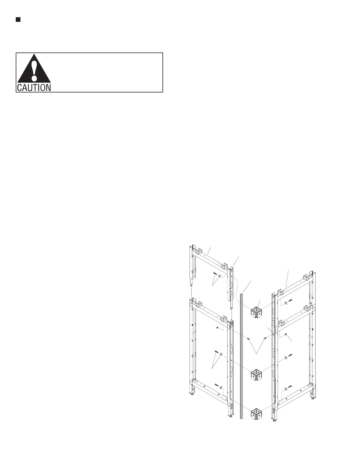
Stacking Sections
(steel frame) - Full-Height
Intersection Assembly
Note: Stacking sections -
full-height intersections are
specified/ordered at time of
original space planning and come
with full-height light shield,
full-height vertical intersection
trim and three connector blocks
as illustrated (Figure 10).
Stacking sections receive tiles,
similar to standard panel frames.
Note: Three-sided
steel-construction stacking
sections (steel frame) utilize
exterior-mounted tiles of either
fabric, markerboard or slat wall
option (Detail F, page 14).
IMPORTANT: Reference
"Connector Block with Spacer Plate
Overview" on page 3, to review the
correct installation procedure of
connector blocks to panel frame
intersections (Detail A).
Important: When stacking
sections are ordered after original
space planning/installation, the
light shield and trim will ship in
two pieces to install in two pieces
(Page 74, Figure 10).
Note: If full-height vertical
intersection trim and full-height
light shield (optional) are
desired after original space plan
installation instead of two-piece
assembly, proceed to "Stacking
Sections - Overview" instructions
on page 67. The steps to follow
and Figure 10 illustrate the
full-height stacking intersection
connection, as ordered at time of
space planning.
Note: Three connector blocks
are required at every full-height
stacking section intersection.
1. Loosely attach two connector
blocks on one panel frame. Each
block is connected using a
3
/
8
-16 x 1
1
/
4
” hex bolt and flat
washer. The middle connector
block mounts near the 30” belt
line and the bottom connector
block mounts at the lowest
mounting hole on the panel
frame (Figure 10). Note: If
the lower panel height is near
the 30” belt line height, a
connector block/hardware can
replace the upper
3
/
8
-16 x
3
/
4
”
bolt and k-lock nut.
3. Next, attach the second
panel frame to the installed
connector blocks of the first
assembly using
3
/
8
-16 x 1
1
/
4
”
hex head bolts and large flat
washers (Figure 10).
4. Tighten all hex bolts securing
panel frames to connector
blocks in the intersection.
Twist the height-adjustable
glides in or out to level the
frames (Figure 10).
3. At intersection conditions,
loosely insert a shorter
3
/
8
-16 x
3
/
4
” hex head bolt to
the top mounting holes of each
intersection panel frame, then
twist on a
3
/
8
-16 k-lock nut.
Note: The nut must be
positioned inside the panel
frame and flat washers are
not required. One at a time,
position a stacking section at
the intersection as illustrated.
Press the posts into the
cavities at the top of the panel
frame. The stacking section
fork will rest on top of the
hex bolt. Tighten the hex
bolt and k-lock nut to secure
the stacking section at the
intersection (Figure 10).
2. Loosely attach one connector
block to the stacking panel
frame. Use a
3
/
8
-16 x 1
1
/
4
” hex
head bolt and large flat washer
to attach the connector block
to the highest mounting hole
on the stacking section
(Figure 10).
3. Loosely attach the second
stacking section to the
connector block on the first
stacking section using a
3
/
8
-16 x 1
1
/
4
” hex head bolt and
large flat washer (Figure 10).
4. Tighten all
3
/
8
-16 x 1
1
/
4
” hex
bolts securing stacking section
to connector blocks at the
intersection (Figure 10).
5. For light shield installation,
reference "Stacking Sections
(aluminum frame) - Full-Height
Intersection Assembly"
instructions on page 9, steps 5
& 6.
Note: Additional instructions
for stacking sections are covered
later in this manual. Reference
"Stacking Sections (steel frame) -
End-of-Run & In-Line Assembly"
instructions on page 14.
 Loading...


