Unite
®
Panel System - Panel Frame Assembly
Assembly Instructions
Assemble units as described herein only. To do otherwise
may result in instability. All screws, nuts and bolts must be
tightened securely and must be checked periodically after
assembly. Failure to assemble properly, or to secure parts
may result in assembly failure and personal injury.
3
1
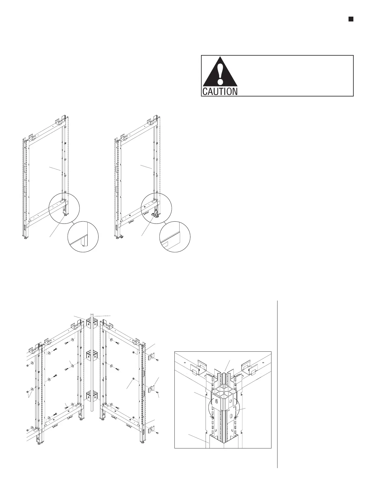
Elevated Base Frame Raceway Base Frame
height-adjustable
glide
base raceway
hinge clip
panel
frame
panel
frame
Panel Frame Overview
Note: If installing stacking sections
onto a pre-existing Unite Panel
System proceed to "Stacking
Sections - Overview" instructions on
page 67.
Unite Panel System frames ship
to the site as welded structures of
various heights and widths. Panel
frames easily connect to each other,
using a single size bolt/washer/nut.
Connections at intersections require
two or three connector blocks. Each
frame has two height-adjustable
glides pre-installed at the base of the
frame to help level the panel system.
The frame assembly becomes the
structure for attaching tiles, trim,
power/data components, storage
and many other accessories.
Your space-planning layout outlines
the panel type, and configuration.
This installation manual instructs
how to assemble the Unite Panel
components into a panel system.
Unite Panel System uses two panel
frame designs, the “Elevated Base
Frame” and the “Raceway Base
Frame” (Figure 1). Assembled and
installed, the Elevated Base Frames
have a 6” opening under the lower
horizontal rail, between the vertical
posts. Raceway Base Frames have
brackets installed under the lower
horizontal rail. Brackets are used for
mounting 10-wire rigid wireways
and base raceway trim to the frames.
Raceway trim fill the 6” opening to
the floor and allow for power and
data outlets.
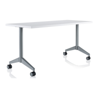
Intersection Connection
Overview
For simplicity, all Unite frame
intersections are secured using one
bolt size:
3
/
8
-16 x 1
1
/
4
” hex head
bolt (48.0115). All intersection
connections use this same bolt. A
3
/
8
-16 k-lock nut and flat washer is
used in some situations (Figure 2).
Connector Block with Spacer
Plate Overview
All intersection and some in-line
intersections require the use of
connector blocks. Connector blocks
attach to the panel frame using a
single
3
/
8
-16 x 1
1
/
4
” hex head bolt
(48-0115) and a flat washer.
Important: Connector blocks are
now pre-assembled with spacer
plates at each of the four faces.
When attaching the connector block
to a frame, it is important that the
spacer plate be left in the “up”
position. The spacer plates maintain
the 3
1
/
2
” standard modularity of the
Unite panel system. When installing
trim, the spacer plates must be bent
straight “down” so the trim can sit
flush with the connector block.
Reconguration: If an intersection
must be reconfigured; the spacer
plate can be lifted “up” and returned
flush with the connector block.
End-of-Run Clips Overview
Trim, installed at the end of frames,
connect to end-of-run trim clips
which must be installed prior to
installing tiles. End-of-run trim clips
attach to frame ends using a single
3
/
8
-16 x
3
/
4
” hex head bolt and
3
/
8
-16
K-Lock nut per clip (Figure 2).
Figure 2-Parts Identification
connector
block
shield
uppermost
hole
flat
washer
lowest
hole
end-of-run
trim clip
/ -16 x /
bolt
8
4
”
3
/ -16
k-lock nut
8
31
/ -16 x 1 /
bolt
84
”
k-lock
nut
and
flat
trim
connector
block
spacer plate
(must be pulled
down when
attaching to
trim)
light shield