4
Unite
®
Panel System - Panel Frame Assembly
Assembly Instructions
Assemble units as described herein only. To do otherwise
may result in instability. All screws, nuts and bolts must be
tightened securely and must be checked periodically after
assembly. Failure to assemble properly, or to secure parts
may result in assembly failure and personal injury.
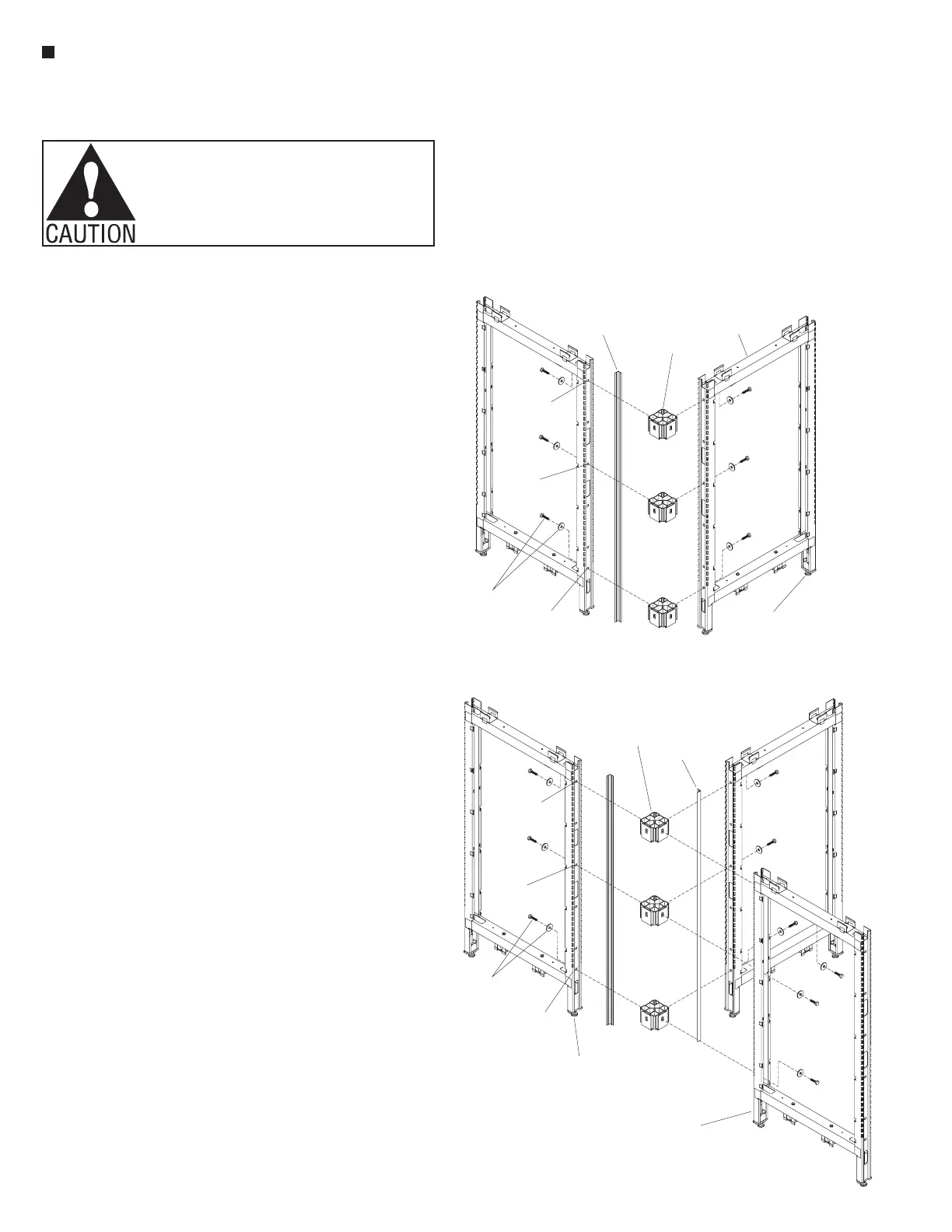
Figure 3-2-Way90,“L” Corner Intersection
°
connector
block
light
shield
uppermost
hole
lowest
hole
beltline
hole
height-adjustable
glide
/ -16 x 1 /
bolt & flat
washer
84
”
panel
frame
Panel Frames - Intersection
Assembly
Important: It is very important to
level the panel system. Know and
mark all high and low spots on
the floor, and make sure to twist
adjustable glides out appropriate
to floor conditions. Always begin
assembling frames together at the
highest point of an un-even floor,
with the glides adjusted
1
/
2
” from
the base of the frame.
Note: If stacking sections are
specified, different guidelines
apply for the placement of
connector blocks. See pages 9
& 10.
1. Assembly of Unite Panel System
frames should begin at an
intersection (90° or 120°). Per the
space-planning layout, locate two
panel frames to be joined together.
Note: If two panel frames being
joined are of different heights,
begin with the lower-height panel,
as the shorter panel determines
the number of connector blocks
required. Proceed to "Panel
Frames - Change-of-Height
Intersection Assembly"
instructions on page 8.
2. Loosely attach connector blocks
to one vertical panel frame using
one
3
/
8
-16 x 1
1
/
4
” hex head
bolt and large flat washer per
connector block (Figures 3, 4 &
5). Attach one connector block at
the lowest mounting hole in the
frame, one at the highest, and the
third approximately 30” from the
floor, near beltway height. If the
panel frame is only 32” high, use
only two connector blocks, one at
the top and one at the bottom (See
Detail C - “Panel Connector Block
Charts,” page 5).
3. Have one person hold the panel
frame (with connector blocks).
Then attach the next panel frame
to the first panel frame using
hex head bolts and flat washers.
Hand-tighten hardware until all
intersection connections are made
(Figures 3, 4 & 5).
4. Tighten all hex bolts at intersections,
then level the panel frames,
twisting the height-adjustable
glides in or out (Figures 3, 4 & 5).
Note: Light shields are available
in 48, 64 & 80” nominal lengths.
The above light shield lengths do
not require cutting when paired
with the same nominal height
panel frame.
5. Begin light shield installation by
first locating the nominal length
plastic light shield that matches
the nominal height panel frame it
installs adjacent to. For nominal
height 32, 40 & 56” panels,
locate a light shield that is longer
than, but closest to the nominal
frame height. When required (for
32, 40 & 56” panel heights), cut
the longer plastic light shield to
size. See Detail A - “Light Shield
Table,” page 5 to determine
proper cut length.
6. Plastic light shields must be
installed after intersections are
assembled and all bolts are
tightened into connector blocks.
Measure and make a mark that
is
5
/
16
” down from the top of the
vertical frame post (Detail B,
page 5). Using the proper length
light shield, position the top of
the shield at that
5
/
16
” mark. Snap
the light shield into the corner of
each connector block such that
you hear a “click”, ensuring that
the light shield is snug at each
connector block.
Note: The bottom of the light
shield should fit flush with the
bottom trim when trim is installed.
The top of the light shield should
fit nearly flush with the underside
of an intersection top cap when it
is installed later.
Tip: A top cap can be temporarily
installed to help locate the top
of the light shield. Snap the light
shield in place such that the top of
the shield is flush with the bottom
of an installed top cap.
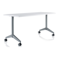
4-3-Way90,“T” Corner Intersection°
connector
block
light
shield
lowest
hole
height-adjustable
glide
/ -16 x 1 /
bolt & flat
washer
84
”
uppermost
hole
beltline
hole
panel
frame