6
Assemble units as described herein only. To do otherwise
may result in instability. All screws, nuts and bolts must be
tightened securely and must be checked periodically after
assembly. Failure to assemble properly, or to secure parts
may result in assembly failure and personal injury.
Unite
®
Panel System - Panel Frame Assembly
Assembly Instructions
uppermost
hole
lowest
hole
beltline
hole
31
/ -16 x 1 /
bolt & flat washer
84
”
panel
frame
120
connector
block
°
120
light
shield
°
glide
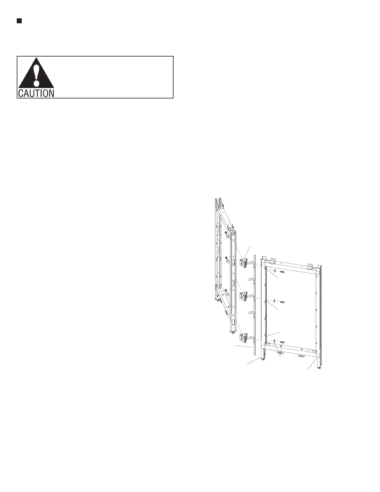
Figure 6 - 2-Way 120 , Corner Intersection
°
120º Panel Frames -
Intersection Assembly
Note: Assembly of 120º panel
frame intersections are similar
to 90º panel frame intersections,
except the design, function and
installation of the light shields
are different between the two.
As shown on pages 4 & 5, 90º
intersection light shields are
made of plastic and have no
tabs. The 120º intersection light
shields are made of metal and
have integral tabs which serve as
spacers for proper panel frame
spacing. Care must be taken
to install 120º intersections
correctly.
Important: It is very important
to level the panel system. Know
and mark all high and low spots
on the floor, and make sure to twist
adjustable glides out appropriate
to floor conditions. Always begin
assembling panels together at the
highest point of an un-even floor,
with the glides adjusted
1
/
2
” from
the base of the frame.
Note: The instructions to follow
outline the assembly of 120º
panel frame intersections using
panel frames of the same height.
Your configuration may vary.
Reference the appropriate 90º
intersections instructions if your
configuration varies. If a 120º
Change-of-Height Panel Frame
intersection is to be assembled,
reference "Panel Frame - Change-
of-Height Intersection Assembly"
instructions on page 8. If a 120º
stacking section (aluminum
frame) intersection is to be
assembled, reference "Stacking
Panel Sections (aluminum
frame) - Full-Height Intersection
Assembly" instructions on
page 9. If 120º stacking section
(steel frame) intersection is to be
assembled, reference "Stacking
Sections (steel frame) -
Full-Height Intersection Assembly"
instructions on page 10.
1. Loosely attach 120º connector
blocks and appropriate length
light shields to one vertical panel
frame using one
3
/
8
-16 x 1
1
/
4
” hex
head bolt and large flat washer
per connector block. Slide the
light shield over the mounting
bolts, between the panel frame
and the connector blocks
(Figures 6 & 7). Attach one
connector block at the lowest
mounting hole in the frame,
one at the highest, and the third
approximately 30” from the floor,
near beltway height. If the panel
frame is only 32” high, use only
two connector blocks, one at the
top and one at the bottom (See
Panel Connector Block Chart,
page 5).
2. Have one person hold the panel
frame (with 120º connector
blocks and light shield attached).
Then attach the next panel frame
and light shield to the first panel
frame using hex head bolts
and flat washers. Hand-tighten
hardware until all intersection
connections are made (Figures
6 & 7).
Note: Multiple frame
intersections require multiple
light shields. Work around the
intersection in a counter-clockwise
direction attaching panel frames/
light shields until all panels are
loosely attached. Light shields
slide in between the panel frame
and connector blocks and then
nest down onto mounting bolts.
This requires that the intersection
remains loose until all frames are
attached at an intersection.
4. Tighten all hex bolts at
intersections, then level the
panel frames, twisting the
height-adjustable glides in or out.
When tightening the bolts, ensure
that all intersection light shields
are properly in place and fully
engaged around the bolt shaft
(Figures 6 & 7).