Unite
®
Panel System - Electrical Installation
Assembly Instructions
Assemble units as described herein only. To do otherwise
may result in instability. All screws, nuts and bolts must be
tightened securely and must be checked periodically after
assembly. Failure to assemble properly, or to secure parts
may result in assembly failure and personal injury.
29
10-wire
rigid wireway
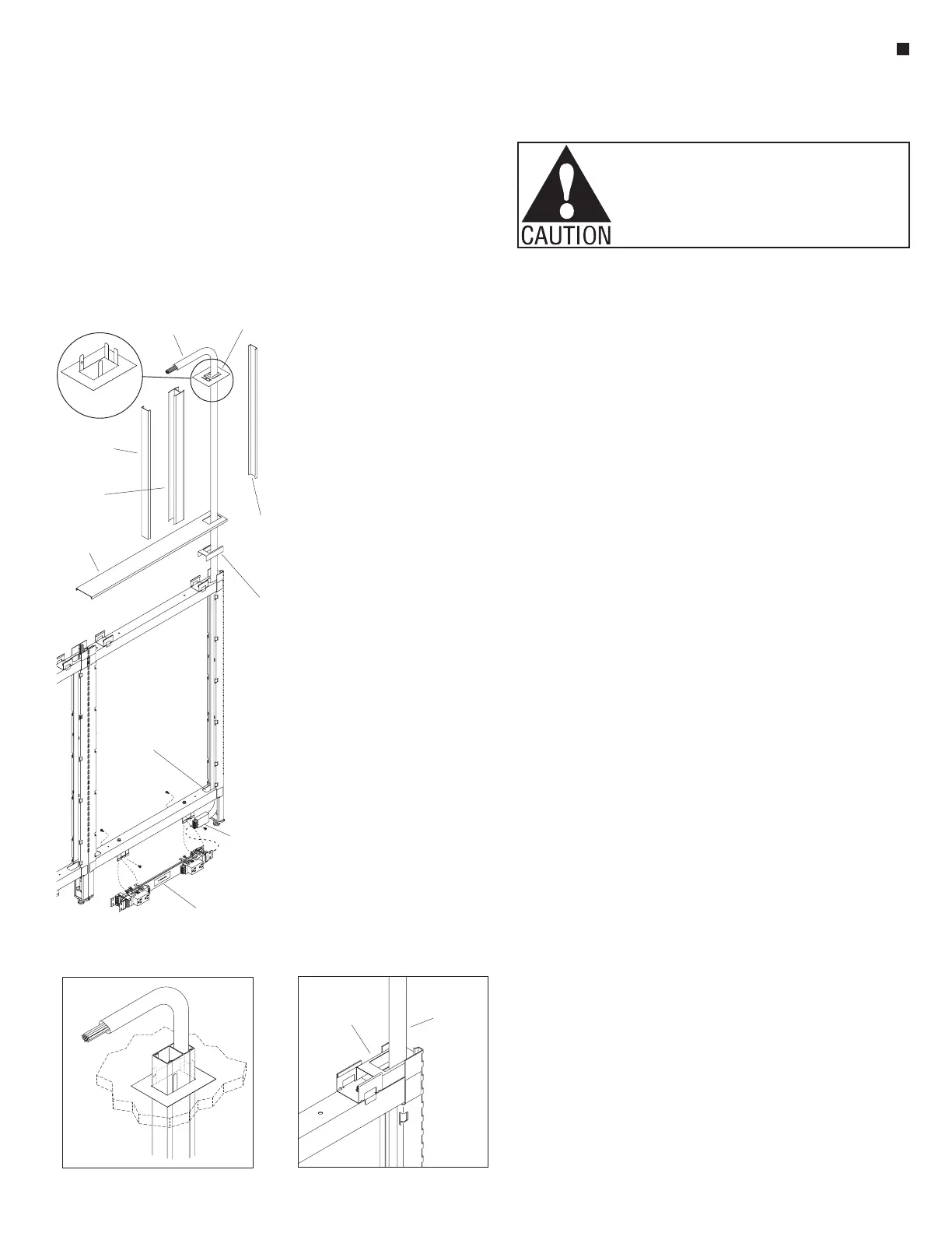
13-10-Wire Top Power Infeed
top infeed
(plug end)
top power infeed
(10-wire end)
top infeed
power pole
cover
top infeed
tabs bent
up
top infeed
panel trim cap
ceiling
trim cap
power pole
retaining clip
notch of lower
horizontal rail
top infeed
power pole
cover
10-Wire Top Power Infeed
Installation
Note: All panel frames must
be mechanically connected
together, with all 10-wire rigid
wireways and panel-to-panel
power connections appropriately
installed before adding power
infeed, or connecting infeed to
power source.
1. Make sure that panel frame to
receive 10-wire top power infeed
is in its final location, and is
plumb and level. At the location
where the top infeed power pole
will set, place a power pole
retaining clip inside the top
trough of the upper horizontal
frame member, with the open end
of the clip facing the end of the
frame. Snap the clip into place so
it sits firmly in the bottom of the
trough (Figure 13).
2. Loosely set the top infeed panel
trim cap onto the upper horizontal
frame, with the power pole
cut-out location right over the
power pole retaining clip
(Figure 13).
3. At the ceiling, directly above the
location where the 10-wire top
power infeed will exit the panel
frame, drop a plumb line to a
corner of the infeed opening in
the top infeed trim cap, transfer
that location to the ceiling, then
carefully mark and cut hole in the
ceiling (
1
/
4
” larger than the inside
hole dimension of the top infeed
panel trim cap) for the top infeed
power pole to go through at a
later step.
4. Position the 10-wire top power
infeed inside the vertical channel
of the panel frame upright, and
route the plug end of the infeed
down through the notch in the
lower horizontal rail as illustrated
(Figure 13).
Note: It is easier to plug the
10-wire top power infeed into
the 10-wire rigid wireway if the
wireway is disconnected from the
wireway mounting brackets first.
5. Remove the screws attaching
the 10-wire rigid wireway to the
wireway mounting brackets,
move the wireway away slightly
and plug the 10-wire top power
infeed into the rigid wireway.
Once secure, re-attach wireway to
mounting brackets (Figure 13).
Note: The top infeed power pole
consists of an assembly of three
extruded pieces which must be
cut to proper length. The outer
pieces are covers. The inner piece
has a smaller cavity for running
data, and the larger cavity is for
running power infeed.
6. Place the assembled top infeed
power pole next to the panel at
the infeed location, and orient the
pole straight up so the top of the
pole touches the ceiling. Add 4”
to the distance from the ceiling to
the top of the panel frame, then
mark and cut the three pieces of
the aluminum top infeed power
pole to that length.
Note: The top infeed power pole
extrusion cover for the power
cavity is shown removed in
Figure 13. Pole and power can be
run up into the ceiling in different
ways, with the covers on or off for
power and data installation. The
steps below outline just one way.
7. Route the 10-wire end of conduit
up through the top horizontal rail
of the panel frame, through the
power pole retaining clip, and the
top infeed panel trim cap. Then
push the 10-wire top power infeed
up into the assembled, cut-to-size
(step 6) top infeed power pole.
Take a ceiling trim cap and bend
the four tabs up, just less than
90° at the side that will face the
ceiling (Figure 13). Slide the
ceiling trim cap onto the top of
the power pole and press it down
8”. Push the 10-wire end of the
power infeed up and out through
the end of the power pole.
8. Push the top of the power pole up
into the opening cut in the ceiling
high enough to allow the bottom
of the pole to move over and fit
down though the rectangular hole
in the top infeed panel trim cap.
Set the bottom of the power pole
down to rest on the power pole
retaining clip (Figure 13).
9. Push the 10-wire top power infeed
the rest of the way up through
the pole into the area above the
ceiling and push the ceiling trim
cap up tight to the ceiling, with
tabs through ceiling opening
(Figure 13 & Detail I).
Note: The top infeed trim cap
must not be snapped into place
until later when panel tiles are
installed.
Note: The power infeeds are to
be connected to the power source
by a qualified electrician who
must follow all state and local
codes at the building site and
check the electrical integrity of the
finished system.
power pole
retaining clip
10-wire
top power
infeed
 Loading...


