Unite
®
Panel System - Panel Frame Assembly
Assembly Instructions
Assemble units as described herein only. To do otherwise
may result in instability. All screws, nuts and bolts must be
tightened securely and must be checked periodically after
assembly. Failure to assemble properly, or to secure parts
may result in assembly failure and personal injury.
15
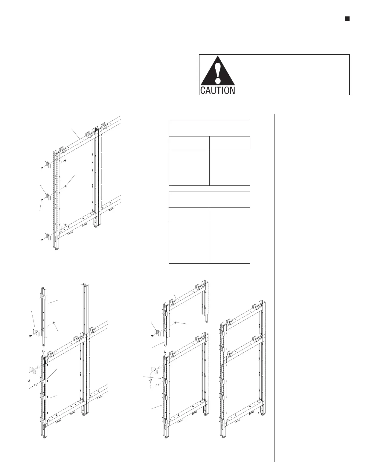
16 - End-of-Run Trim Clip
end-of-run
trim clip
end-of-run
panel frame
33
/ -16 x /
bolt
84
”
3
/ -16
k-lock nut
8
End-of-Run Trim Clip Charts
Same Height -or Shorter End
Panel Frame at Change-of-Height
Panel
Height
32”
40”
48”
56”
64”
2
3
3
3
3
Trim Clips
Required
Taller Panel Frame
at Change-of-Height
Taller Section
Height
8”
16”
24”
32”
40”
48”
1
2
2
2
3
3
Trim Clips
Required
End-of-Run Trim Clip
Installation
Note: End-of-run trim clips are
installed to end-of-run panel
frames to hold vertical trim in
place. End-of-run clips must be
installed prior to installing tiles.
1. End-of run trim clips attach to the
frame using a
3
/
8
-16 x
3
/
4
” hex
head bolt and
3
/
8
-16 k-lock nut.
All end-of-run frames, except
the shortest 32” high frame will
require three clips installed (see
End-of-Run Trim Clip Charts).
Attach one end-of-run clip at
the lowest mounting hole in the
frame, one clip at the highest,
and the third end-of-run clip
approximately 30” from the floor,
near beltway height (Figure 16).
2. For “stacking sections (aluminum
frame) with glass, perforated
steel or steel top frames”
(shown Figure 17), or “stacking
sections (steel frame) with fabric,
markerboard or slat wall tiles”
(shown Figure 18), end-of-run
trim clips install to the upper
frame (see “Upper Panel Frame
at Change-of-Height” chart below
for quantity). For the
“end-of-run lower panel frame”
(Figure 18), the uppermost
end-of-run clip must be
re-installed one hole location
below the top mounting hole. This
is so the “fork” of the stacking
section can install to the end of
the lower panel frame.
3. Loosely insert a
3
/
8
-16 x
3
/
4
” hex
head bolt to the top mounting
hole of the lower end panel frame,
then twist on a
3
/
8
-16 k-lock nut.
The nut must be positioned inside
the panel frame and flat washers
are not required.
4. Slide/tap the stacking section
down at end of the panel frame
as illustrated, with the notch of
the fork behind the
3
/
8
-16 x
3
/
4
”
hex bolt. Tighten the hex bolt and
k-lock nut to secure (Figures 17
& 18).
18 - Stacking Sections (steel frame)
end-of-run
trim clip
end-of-run
stacking
section
end-of-run
lower panel
frame
top
end-of-run
trim clip
fork
3
/ -16
k-lock nut
8
17 - End-of-Run Clips with
Stacking Sections
3
/ -16
k-lock nut
8
-run
trim clip
vertical
stacking
post
end-of-run
lower panel
frame
top
end-of-run
trim clip
(moved down)
 Loading...


