Unite
®
Panel System - Gallery Panel Installation
Assembly Instructions
Assemble units as described herein only. To do otherwise
may result in instability. All screws, nuts and bolts must be
tightened securely and must be checked periodically after
assembly. Failure to assemble properly, or to secure parts
may result in assembly failure and personal injury.
37
End-of-Run Dual-Sided
Two-Piece Gallery Panel
Installation
Note: Sizes for high-pressure
laminate (HPL) and thermally-fused
laminate (TFL) gallery panel models
are unique and different. However,
both HPL and TFL gallery panels
install the same. The following
instructions apply to both HPL and
TFL models. All end-of-run gallery
panels ship with an 11-gauge steel
plate which fastens to the inside face
of the gallery panel. Glides are
pre-installed at each bottom corner
of all gallery panels.
Note: The following instructions
assume the gallery panel is the same
height as the Unite panel run. If
there is a change-of-height between
gallery or Unite panel, additional
trim will be required.
Preparation: If the installation is
new, gallery panels should be treated
the same as Unite panel frames,
and must be installed prior to tiles
and trim. In some cases, the gallery
panel functions as a return and may
act as a support for a Unite panel
run.
If the installation is a retrofit or
add-on, then Unite tiles must be
removed from the end of the Unite
panel run and set aside. The bottom
tile channel and raceway trim can
remain in place.
In either case, the Unite panel
run must be installed and leveled
per standard Unite, panel frame
installation instructions.
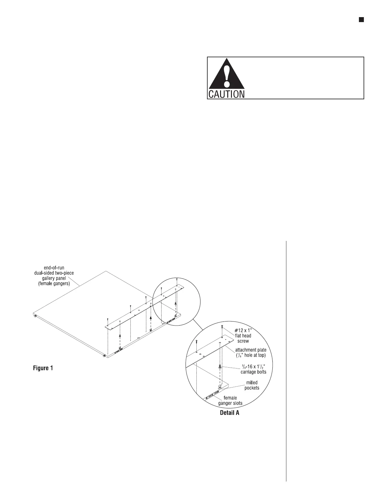
Note: End-of-run, dual-sided
two-piece gallery panels are unique
in that they require separate right and
left panels. The panels are shipped
with pre-installed ganger cleats,
which are designed to pull and snug
the two panels together.
1. Set the panel with male ganger
hooks to the side. Lay the gallery
panel with female gangers onto a
soft protective surface on the floor
so that the face with mounting
holes faces up. Place three
3
/
8
-16 x 1
1
/
2
” carriage bolts
loosely into the round, milled
pockets with the bolt head resting
in the pocket, and the shank
pointing upward. Place one bolt
in the top hole, one in the lowest
hole and the third in any hole near
the middle of the panel. Not all
holes will receive bolts and only
half of a pocket will be milled
(Figure 1 & Detail A).
2. Locate the top of the 11-gauge
attachment plate. The top has
a
1
/
8
” hole at the center of the
plate to identify the top. Align the
top edge of the attachment plate
with the top of the gallery panel
(opposite the bottom glides). Lay
the plate down and allow the three
carriage bolts to protrude through
three square holes in the plate
(Figure 1 & Detail A). Note: The
plate will be half exposed so that
the gallery panel with the male
gangers can be installed at a later
time.
Caution: Make sure the
shoulders of the carriage bolt are
nested in each square pocket and
that the plate lays flush against
the face of the panel.
3. Install #12 x 1” flat head screws
into each counter-sunk hole as
illustrated. Each hole should
contain a pre-drilled
1
/
8
” diameter
pilot hole in the panel. Snug each
screw tight (Figure 1 & Detail A).
Caution: Do not over-torque
screws which could strip the
threads in the particle board.