36
Unite
®
Panel System - Gallery Panel Installation
Assembly Instructions
Assemble units as described herein only. To do otherwise
may result in instability. All screws, nuts and bolts must be
tightened securely and must be checked periodically after
assembly. Failure to assemble properly, or to secure parts
may result in assembly failure and personal injury.
End-of-Run Dual-Sided &
Single-Sided Gallery Panel
Installation (cont.)
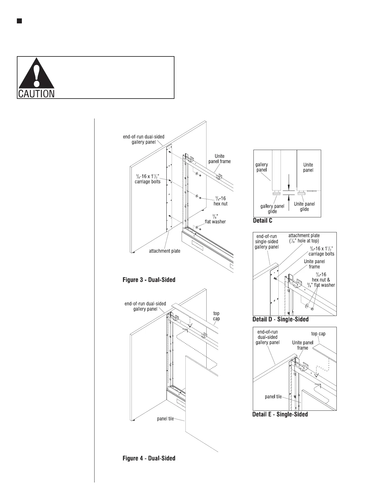
4. Gallery panel glides should be
adjusted at this point to ease
panel installation. Measure the
distance from the bottom of the
Unite panel raceway trim, or
lifted foot shroud, down to the
floor. Adjust the glide from the
bottom edge of the gallery panel
the same distance. This step may
require attaching a raceway cover
or foot shroud to the Unite panel
frame (Detail C).
5. Using two people, lift and
position the gallery panel
perpendicular to the end of the
Unite panel run. If the glides were
adjusted properly, the bottom of
the gallery panel should align
with the Unite trim bottom, all
should align and no lifting should
be required. The three bolts
should align with three mating
holes in the Unite panel frame
(Figure 3 & Detail D).
6. Push the gallery panel until the
attachment plate contacts the
vertical post of the Unite frame,
and the three bolts extend on the
inside of the vertical post. Install
three
3
/
8
” flat washers and hex
nuts to the
3
/
8
-16 carriage bolts.
Use a deep-well,
9
/
16
" socket, and
tighten each nut securely
(Figure 3 & Detail D).
Caution: Ensure both glides are
sitting firmly on the floor under
the gallery panel weight, such
that the panel does sway or move
easily.
7. Install Unite panel run tiles, top
cap & base raceway trim. See Tile
Installation section starting on
page 45 (Figure 4 & Detail E).