34
Unite
®
Panel System - Electrical Installation
Assembly Instructions
Assemble units as described herein only. To do otherwise
may result in instability. All screws, nuts and bolts must be
tightened securely and must be checked periodically after
assembly. Failure to assemble properly, or to secure parts
may result in assembly failure and personal injury.
data filler
plate
11
/ -20 x 2 /
thread-forming
screw
44
”
receptacle box &
receptacle box &
Z-bracket assembly
Chicago
mounting
bracket
Chicago
filler plate
Chicago
bezel plate
Chicago base
raceway trim
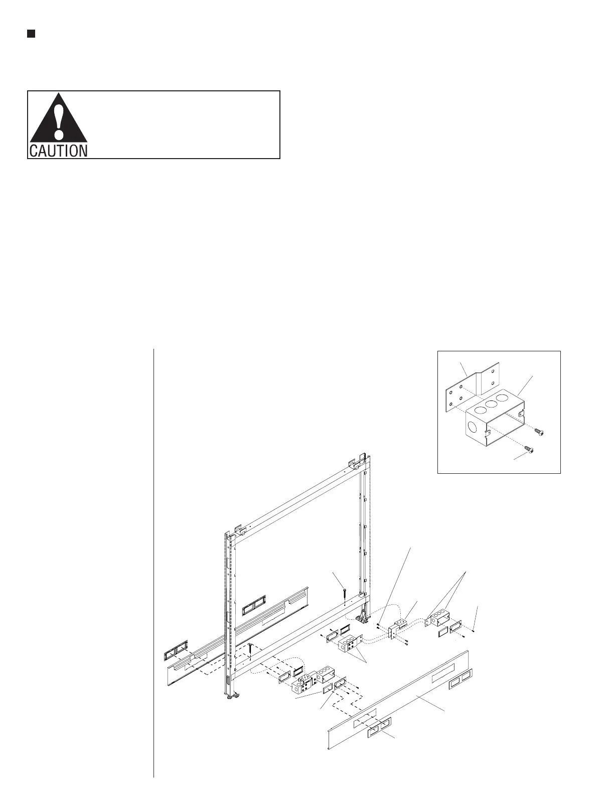
20-Chicago Hardwired Base Power Infeed -36 through 72 Panel Widths
15
/ -20 x 2 /
Phillips thread-forming
screw (46.0195)
416
”
filter
Chicago Hardwired Base
Power Infeed Installation - 36”
through 72” Panel Widths
Note: The Chicago Hardwired
steel receptacle boxes may mount
to open at both sides of the panel
frame base, but the boxes are
staggered to not be back-to-back.
Frames of 24” or 30” wide
can accommodate only one
receptacle box per side, while
36” through 72” wide frames can
accommodate two receptacle
boxes per side.
Chicago Hardwired - 36
through 72” Panel Width
1. Position a Z-bracket to the back
of a steel receptacle box, and
attach bracket to box using
1
/
4
-20 x
5
/
16
” Phillips
thread-forming screws (46.0195)
as illustrated (Detail M).
Assemble all remaining frame
boxes and Z-brackets together at
this time. The receptacle box &
Z-bracket assemblies are
non-handed, so can be used on
either side of the frame.
2. Using
1
/
4
-20 x
5
/
16
” Phillips
thread-forming screws (46.0195)
screws, attach a Chicago
mounting bracket to each
receptacle box & Z-bracket
assembly as illustrated. For
36” through 72” wide frames,
two frame box & Z-bracket
assemblies will attach to each
Chicago mounting bracket, to
face the outside of each side of
the frame. Orient the parts for
assembly such that the screw
goes through the Chicago bracket
and threads into the Z-bracket
(Figure 20).
3. If the lower panel frame rail has
two brackets mounted under it,
remove the
1
/
4
-20 x 2
1
/
4
”
thread-forming screws securing
them. Discard the brackets but
retain the screws. Orient the
Chicago mounting brackets (with
receptacle & Z-bracket attached)
under the holes in the lower
panel frame rail and secure the
Chicago mounting brackets to the
frame rail using a
1
/
4
-20 x 2
1
/
4
”
screw (Figure 20).
Note: The power infeeds are to
be connected to the power source
by a qualified electrician who
must follow all state and local
codes at the building site and
check the electrical integrity of
the finished system.
4. Install conduit, wiring and
receptacles per Chicago Electrical
Codes.
5. Place a Chicago filler plate over
the receptacle box as illustrated
and secure with two filler plate
screws (Figure 20).
6. Install Chicago base raceway
trim in the same manner as
standard Unite. Chicago base
raceway trim are different than
standard as the cut-outs are
in unique locations for this
application (Figure 20).
7. Snap the Chicago bezel plate into
the Chicago base raceway trim.
Chicago bezel plates are different
than standard as they have the
1
/
2
” deep snap tabs removed.
Snap the data filler plates into the
Chicago bezel plates if no data
cables are used at that location.
The data port accepts modular
furniture data port covers or data
jacks (Figure 20).
Z-bracket
receptacle
box
M
15
/ -20 x 2 /
Phillips thread-forming
screw (46.0195)
416
”