9
ASSEMBLY INFORMATION
EN 126
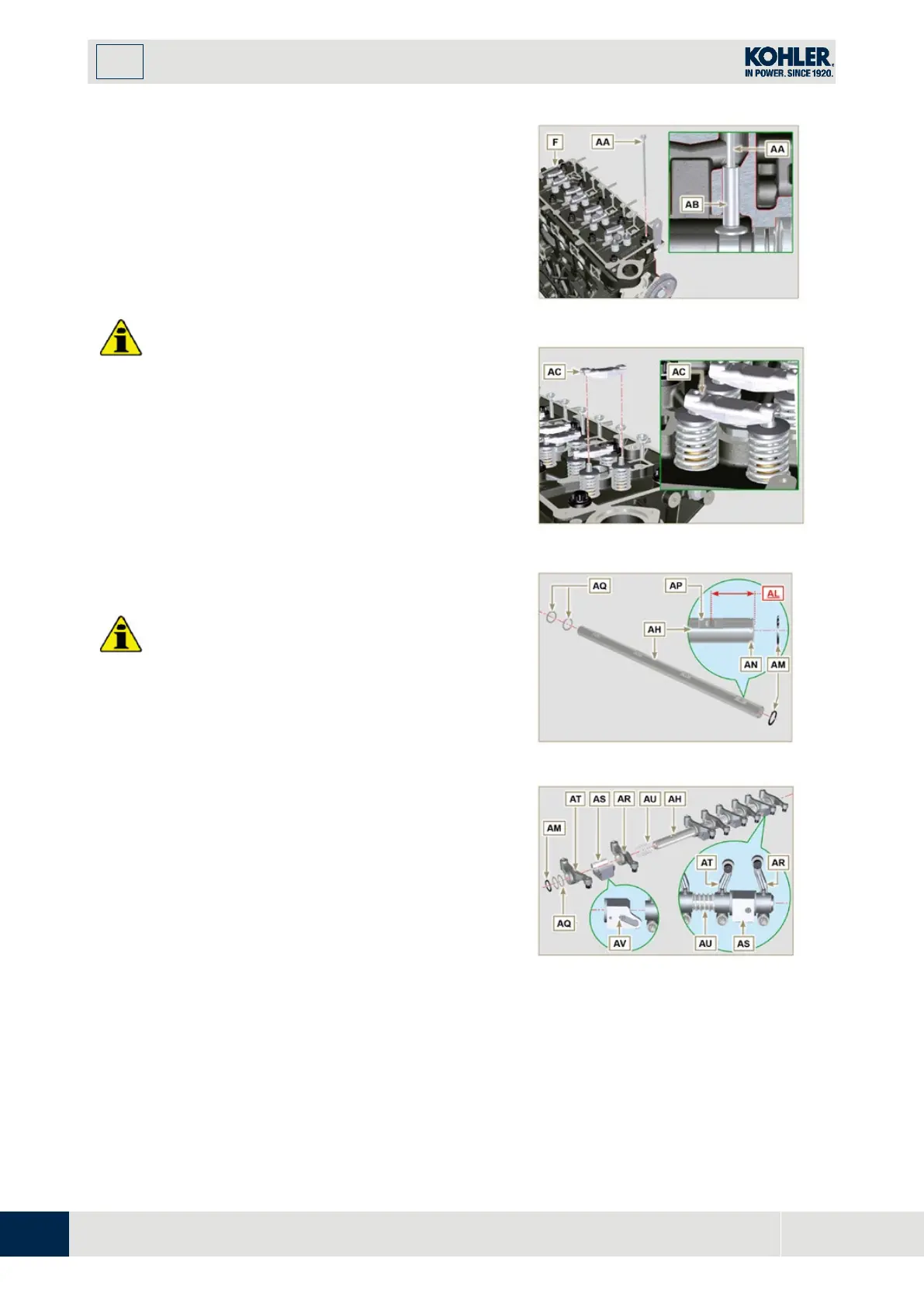
9.7.6 Rods and valve bridges
1.
Insert the rocker control rods AA into the niches of
the head F.
I
mportant
•
Properly centre the rods AA into the spherical
housing of the camshaft tappets AB.
2.
Mount the valve bridge AC on to the pairs of
discharge and suction valves.
I
mportant
•
To correctly position the rocker arms, turn the
rocker arm pin AH with the lower height AL
towards the timing system side as in Fig.9.54.
•
The discharge rocker arm AT is shorter than the
suction arm AR.
1.
Fit the lock ring AM into the seat AN of the rocke
r
a
rm pin AH.
2.
Position the pin AH with the screw support surface
AP f
acing upwards and insert the 2 shoulder rings
AQ.
3.
Insert in sequence the suction rocker arm AR, the
holder AS and the discharge rocker arm AT in the
pin AH.
4.
Insert the spring AU in the pin AH.
5.
Repeat points 3, 4 for all the rocker arms.
NOTE: The holder AV must be fitted with the las
t
p
air of rocker arms towards the flywheel.
6.
Insert 2 shoulder rings AQ and the lock ring AN to
lock all the components inserted in the pin AH.
NOTE: The spring AU ensures that the supports
AS and AV are kept in place.
Fig 9.54
F
ig 9.55

 Loading...


