11
INFORMATION ABOUT OPTIONAL
COMPONENTS
EN 154
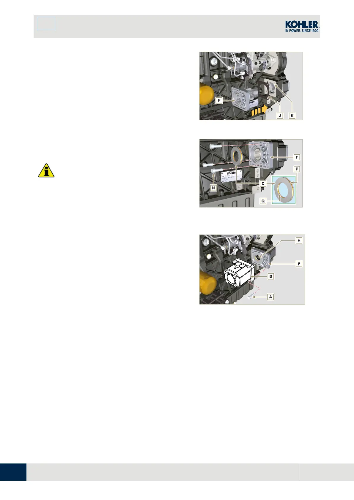
Position the flange
on the crankcase
i
nserting the gasket J, and inserting the gear H
up to the stop on the bearing L (Fig. 11.31).
Secure the flange F using the screws N
(tightening torque at 25 Nm).
I
mportant
•
Always replace the gaskets P and Q at each
assembly.
5.
Insert the centring ring C in the flange F up to
the stop.
Fig 11.19
6.
Insert the pump B on the flange F engaging the
gear H.
7.
Secure the pump B using the screws A on the
flange F (tightening torque at 25 Nm).

 Loading...


