6
INFORMATION FOR REPLACING THE
FUNCTIONAL UNITS
EN 66
3. Assemble the parts
P, Q, R
and fit the parts so
assembled on the injector
Z
.
Fig 6.22
4. Insert tool
ST_51
on the injectors junctions
Z
(detail
X1
).
5. T
ighten the screw
P
(tightening torque to
2
0
Nm
)
Fig 6.23
NOTE
: Click on the right to play the procedure.
https://www.youtube.com/embed/Kcv-
_3Edask?rel=0
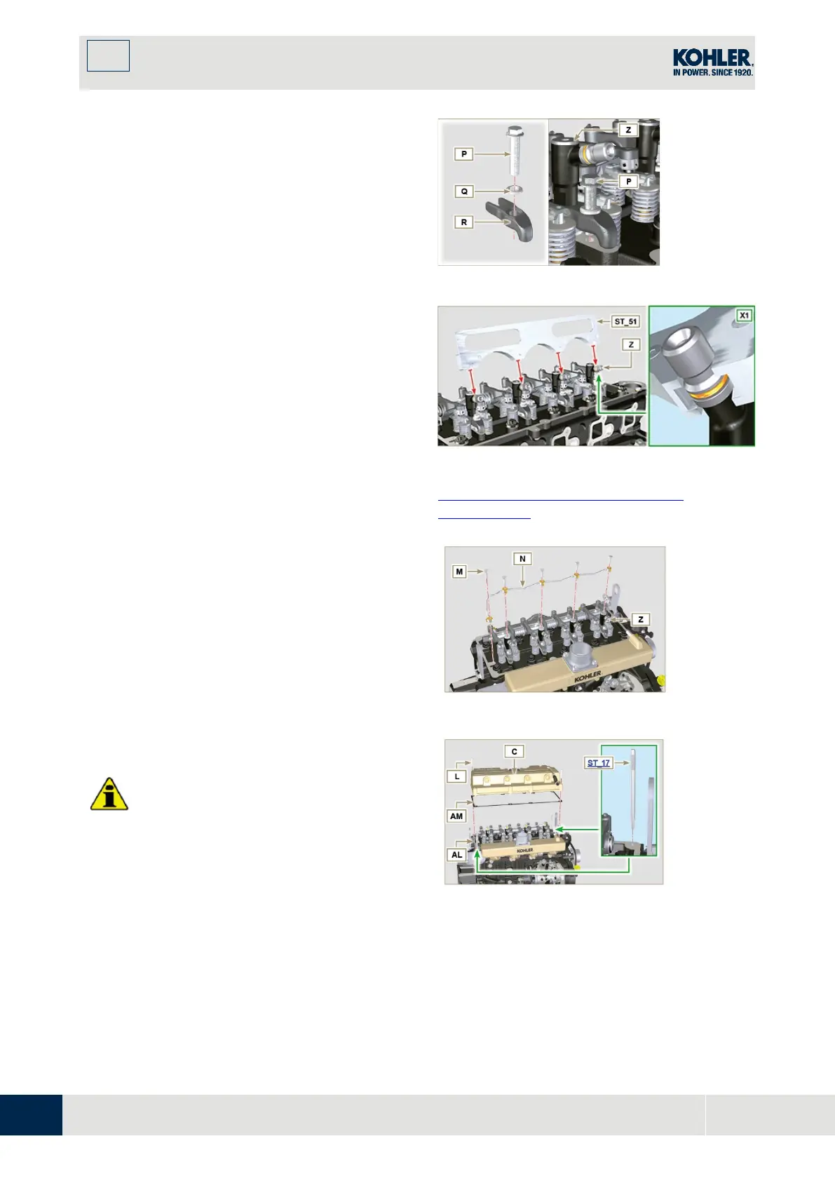
6.1.8 Assembly of the injector return pipes
1.
Position the tube N on the injectors Z, an
d
ti
ghten screws M (tightening torque to 14
Nm).
Fig 6.24
6.1.9 Assembly Rocker arm cover
Important
•
The gasket AM between the rocker arm
cover and the cylinder head must always be
r
eplaced every time it is disassembled.
1.
Position the two guide pins ST_17 befor
e
m
ounting the rocker arm cover.
2.
Position the gasket AM on the head AL
respecting the fastening screw holes L.
3.
Attach the rocker arm cover C on the head
AL with the screw L adhering to the
tightening sequence shown in F ig. 6.27
Fig 6.25

 Loading...


