INFORMATION FOR REPLACING THE
FUNCTIONAL UNITS
6
65
EN
a screwdriver to guide the nut
AN
on the shaft
AP
in order to avoid the fall of it into the timing
cover
AQ
- tightening torque at
70 Nm
).
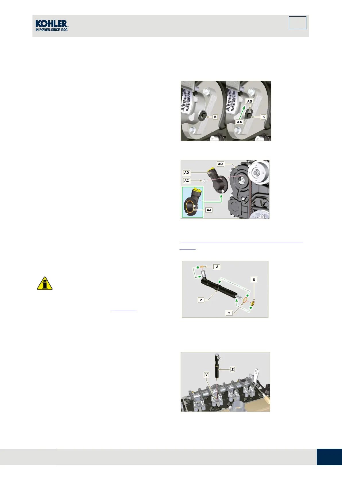
4. Undo the capscrew
K
and shift the slotted
plate
AB
in the direction of arrow
AA
.
5. Tighten screw
K
(tightening torque to
5.5 Nm
)
.
T
he injection pump is unlocked.
6. Remove the tool
ST_30
and
ST_34
.
Fig 6.18
NOTE
: Always replace the gasket
AJ
after each
assembly.
7. P
osition the gasket
AJ
in the set on the flange
AD
.
8. Fix the flange
AD
on the crankcase
AQ
with the
screws
AC
(tightening torque at
10
Nm
).
Fig 6.19
NOTE
: Click on the right to play the procedure.
https://www.youtube.com/embed/RJLCkTqlczU
?rel=0
Important
•
To prevent damaging the injection system,
the protection caps (Par. 2.9.7
) m
ust be
removed during assembly.
1.
L
ubricate the gaskets U, T, S and fit them
on the injector Z.
Fig 6.20
2. Fit the injector
Z
in the sleeve
V
.
Fig 6.21

 Loading...


