6
INFORMATION FOR REPLACING THE
FUNCTIONAL UNITS
EN 64
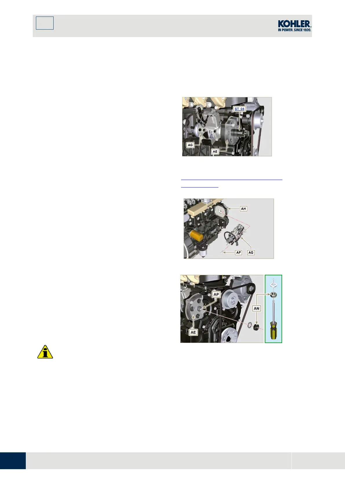
Be careful that the nut AN does not fall into
the timing cover.
13. Screw the tool
ST_04
on the gear AE.
14. Loosen the screws
AF
.
15. Ti
ghten the screw of tool
ST_04
to disconnect
the
injection pump
AG
from the high pressure
pump control gear
AE
.
16. Undo the screws
AF
and extract the injection
pump
AG
.
17. Undo and remove the tool
ST_04
.
F
ig 6.15
NOTE
: Click on the right to play the procedure.
https://www.youtube.com/embed/zqY-
GFl8lG0?rel=0
6.1.6 Injection pump assembly
W
arning
•
Before assembling the new pump AG,
make sure that plate AB can move freely
and that fastening capscrews K are no
t
l
oose (the pump sold as a spare part is
supplied with the cylinder injection timing
blocked N° 1).
•
Ensure that the coupling surfaces on shaft
AP and gear AE are free from impurities
and lubrication residues.
•
Remove the guard cap only when the pipes
are reconnected.
•
Do not remove the tool ST_30.
1. Mount the injection pump
AG
, inserting the
shaft
AP
in the gear
AE
.
Important
•
Always change screws AF with new ones or
apply Loctite 270 to the threads.
2. Clamp the screws
AF
on the crankcase
AH
(tightening torque at
25 Nm
).
3. E
nsure that the correct advance value has
remained unchanged, tighten nut
AN
on shaf
t
AP
(
as shown in
Fig.
6.17,
is allowed the aid o
f
F
ig 6.16
Fig. 6.17

 Loading...


